
Achieving Optimal Central Venous Catheter Position: Evaluation of Radiographic Landmarks for Accuracy and Inter-observer Reliability in Locating the Cavoatrial Junction
ORIGINAL ARTICLE
Achieving Optimal Central Venous Catheter Position: Evaluation of Radiographic Landmarks for Accuracy and Inter-observer Reliability in Locating the Cavoatrial Junction
KW So, HL Tsui, SM Yu, CH Suen, CW Choi, PY Chu, JCS Chan
Department of Radiology and Organ Imaging, United Christian Hospital, Hong Kong
Correspondence: Dr KW So, Department of Radiology and Organ Imaging, United Christian Hospital, Hong Kong. Email: skw520@ha.org.hk
Submitted: 25 Apr 2021; Accepted: 27 Sep 2021.
Contributors: KWS, SMY, CHS and JCSC designed the study. KWS, CHS, CWC, PYC and JCSC acquired the data. All authors analysed the
data. KWS, HLT, CHS and CWC drafted the manuscript. KWS, HLT, SMY, PYC and JCSC critically revised the manuscript for important
intellectual content. All authors had full access to the data, contributed to the study, approved the final version for publication, and take
responsibility for its accuracy and integrity.
Conflicts of Interest: As an editor of the journal, CHS was not involved in the peer review process. Other authors have disclosed no conflicts of interest.
Funding/Support: This research received no specific grant from any funding agency in the public, commercial, or not-for-profit sectors.
Data Availability: All data generated or analysed during the present study are available from the corresponding author on reasonable request.
Ethics Approval: This retrospective study was approved by the Kowloon Central/Kowloon East Cluster Research Ethics Committee (Ref: KC/KE-20-0278/ER-3). Written informed consent was waived by the Committee due to the retrospective nature of the study.
Abstract
Objective
We sought to compare three popular radiographic landmarks for their accuracy and inter-observer
reliability in determination of the cavoatrial junction (CAJ) by analysing the anteroposterior scout and
electrocardiogram-gated coronary computed tomographic angiography (CTA) images.
Methods
CTA image data of 148 patients were assessed. The position of the CAJ defined by CTA was regarded as
the gold standard. The median vertical distance between the CAJ and three radiographic landmarks (two vertebral
body units [vertebrae plus discs] below the carina, the superior aspect of the right heart border, and the intersection
of the bronchus intermedius with the right heart border) were assessed and compared using the Kruskal–Wallis
test. For inter-observer reliability between two radiologists, each with at least 4 years of experience, intra-class
correlation (ICC) was analysed.
Results
The median vertical distances between the CAJ and two vertebral body units below the carina, the superior
aspect of the right heart border, and the intersection of the inferior wall of the bronchus intermedius with the
right heart border were 5.1 mm (0-24.6), 10.2 mm (1-45.2) and 9.8 mm (0.8-45.8), respectively. The radiographic
landmark of two vertebral body units below the carina provided the closest estimation of the CAJ (p < 0.001).
It also demonstrated higher ICC (0.931, 95% confidence interval [CI]=0.905-0.950) than the other two (0.833,
95% CI=0.768-0.880 and 0.860, 95% CI=0.805-0.899, respectively).
Conclusion
Among the three popular radiographic landmarks for the CAJ, we found that a point two vertebral
body units below the carina provided the most accurate estimate of CAJ location.
Key Words: Catheterization; Right atrium; Multidetector computed tomography; Radiography, thoracic; Vena Cava, Superior
中文摘要
實現最佳中心靜脈導管位置:評估放射學標誌在定位腔房交界處的準確性和觀察者間一致性
蘇建偉、徐愷靈、余燊明、孫振航、蔡雋煒、朱炳容、陳志生
目的
我們通過分析前後位探查圖像和心電門控冠狀動脈CT血管造影 (CTA) 圖像來比較三個常用的放射學標誌在確定腔房交界處 (CAJ) 的準確性和觀察者間一致性。
方法
對148例患者的CTA圖像數據進行評估。CTA定義的CAJ位置視為黃金標準。CAJ與三個放射學標誌(氣管隆突下方兩個椎體單位(椎體加椎間盤)、右心邊界的屈曲以及中間支氣管與右心邊界的交點)之間的中位垂直距離進行了評估和使用Kruskal–Wallis檢驗進行比較。對於兩位有最少4年經驗的放射科醫生之間的觀察者間一致性分析了組內相關性 (ICC) 值。
結果
CAJ與氣管隆突下兩個椎體單位、右心邊界上側、中間支氣管下壁與右心邊界交點的中位垂直距離分別為5.1毫米(0-24.6)、10.2毫米(1-45.2)和 9.8毫米(0.8-45.8)。氣管隆突下方兩個椎體的影像學標誌提供了最接近CAJ 的估計值(p < 0.001)。它有比其他兩個放射學標誌(0.833,95% 置信區間=0.768-0.880和0.860,95%置信區間=0.805-0.899)更高的ICC(0.931,95%置信區間=0.905-0.950)。
結論
在CAJ的三個常用的放射學標誌中,我們發現氣管隆突下方兩個椎體單位的點提供了最準確的CAJ位置估計。
INTRODUCTION
Central venous catheter (CVC) placement, including
subclavian lines and peripherally inserted central
catheter lines, is a common procedure performed
by interventional radiologists or clinicians for fluid
management of critically ill patients or when prolonged
intravenous infusion is required. The optimal position of
the CVC tip remains controversial.[1] Tips located near or
within the right atrium have been described to carry a risk
of dysrhythmias and rarely, cardiac perforation.[2] On the
other hand, tips located outside the heart are associated
with venous thrombosis.[3] [4] [5]
The Association for Vascular Access, formerly known as
the National Association of Vascular Access Networks,
proposed a guideline in 1998 that tips should be located
in ‘the lower one-third of the superior vena cava (SVC),
close to the junction of the SVC and right atrium’.[6] Two
other studies recommended tips should be located at the
cavoatrial junction (CAJ).[4] [5] Therefore, positioning of
tips at the CAJ is a popular approach.
The CAJ is defined by the junction of the SVC and the
true right atrium, consisting of a thickened ring of tissue formed by the crista terminalis anteriorly and the crista
dividens posteriorly. These two cristae constitute the
embryonic transition from the sinus venosus to the true
atrium and thus form the anatomic CAJ.[7]
The cristae defining the CAJ are only visible on cross-sectional
imaging such as computed tomography and
magnetic resonance imaging. The CAJ cannot be directly
visualised on conventional chest radiographs, which is
the modality of choice to confirm tip position during
and after CVC placement. Several studies have been
performed to define reliable landmarks that are visible on
a chest radiograph to act as a surrogate for the position
of the CAJ. These studies proposed three surrogates
based on visible landmarks in chest radiographs that
help radiologists define the CAJ in chest radiographs:
(1) two vertebral body units (inferior endplate to inferior
endplate including the intervening disc) below the
carina,[7] (2) the intersection of the inferior wall of the
bronchus intermedius with the right heart border,[8] and
(3) the superior aspect of the right heart border.[8] These
studies are descriptive in nature and there is no direct
comparison between these radiographic surrogates in
terms of accuracy and inter-observer reliability.
The primary outcome of this study was to determinate the radiographic surrogate marker visible in the calibrated
anteroposterior (AP) scout topogram which provides
the best estimation of the CAJ position with reference
to electrocardiographic (ECG)-gated coronary computed
tomographic angiography (CTA) as a gold standard.
The secondary outcome was to assess the radiographic
surrogate marker carrying the best inter-observer
reliability.
METHODS
Study Population
The initial study population included 188 patients
(85 men and 103 women) undergoing contrast-enhanced
coronary CTA at a regional hospital from 1 October
2018 to 1 October 2019. The exclusion criteria were
as follows: omission of the post-contrast study due to
a high calcium score as per department protocol, spinal
disease (including severe lordosis or a history of spine
surgery), and absence of an AP scout topogram. In total,
four cases of spinal disease, four cases without an AP
scout topogram, and 32 cases without contrast CTA were
excluded, leaving a total of 148 cases for analysis.
Image Acquisition
Patients were referred for CTA due to symptoms of
coronary artery disease. They were given 50 to 100
mg metoprolol (beta blocker) 45 to 60 minutes prior to
scanning if their pulse rate was >65 beats per minute
(bpm) and systolic pressure was >110 mm Hg, and they
were routinely given sublingual short-acting 200 mg
nitroglycerin 3 to 5 minutes prior to the scan if systolic
blood pressure was >110 mm Hg.
A non-contrast AP scout image during breath holding
was first acquired for localisation of anatomical
structures. Non-ionic intravenous contrast material
with 350 mgI/mL followed by a 50 mL saline flush was
injected for the patients without a history of allergy to
iodinated contrast. For patients with known allergy
to iodinated contrast, following steroid cover (40 mg
prednisone per dose) at 2 and 12 hours prior to scanning,
iodixanol 320 mgI/mL was administered. The volume of
contrast depended on the estimated scanning time, which
was calculated according to patient’s heart rate and the
flow rate (5 mL/s). Contrast was injected through an 18G
intravenous catheter in the right antecubital fossa.
A bolus triggering technique was employed to ensure
optimal timing of the imaging. A region of interest
was placed on the descending thoracic aorta and the monitor delay was 10 seconds. The scan was triggered
with a 7-second delay when 100-Hounsfield unit (HU)
increment was detected at the descending thoracic aorta.
For patients with a stable heart rate <65 bpm, prospective
ECG gating was employed. Retrospective ECG gating
was employed if a patient’s heart rate was irregular or
≥65 bpm.
Scanning extended from the level of the proximal
ascending aorta to below the inferior margin of the heart
including the pericardium. A 64-multidetector computed
tomography scanner (SOMATOM Definition AS+;
Siemens Medical System, Siemens, Erlangen, Germany)
was used with the following parameters: collimation
0.625 mm × 64 = 4 cm; rotation time: 0.3 s, 140 kVp;
tube current: 300 to 600 mAs; field of view: 50 cm; pitch:
0.18 to 0.24 (depending on heart rate); matrix: 512 × 512;
image reconstruction: kernels (I26f); reconstruction slice
thickness: 0.75 mm with 0.4-mm increments.
Image Evaluation
Images including between 68% and 72% of the
R-R interval were retrieved for evaluation and were
reconstructed into axial and sagittal planes. Image
analysis was performed on a commercially available
picture archiving and communication system workstation
(Centricity Universal Viewer Version 6.0; GE
Healthcare, Chicago [IL], United States). The standard
CTA window settings for evaluation were window width = 500 HU and window level = 40 HU.
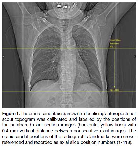
The axial positions in the scout images were correlated to the tube position (Figure 1). The craniocaudal positions of
the CAJ and the landmarks of interest were recorded. The
absolute distance between the radiographic landmarks
and the CAJ determined by CTA (gold standard) were
calculated.
Figure 1. The craniocaudal axis (arrow) in a localising anteroposterior
scout topogram was calibrated and labelled by the positions of
the numbered axial section images (horizontal yellow lines) with
0.4 mm vertical distance between consecutive axial images. The
craniocaudal positions of the radiographic landmarks were cross-referenced and recorded as axial slice position numbers (1-418).
One radiologist with 6 years’ experience of radiographic
and CTA imaging assessed the CTA images, without
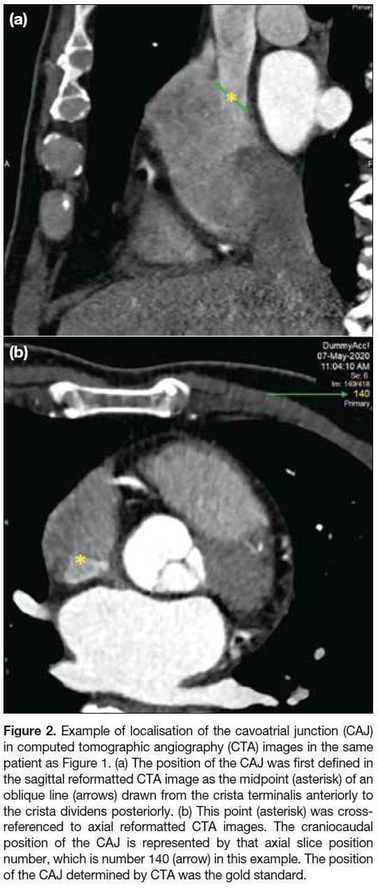
reference to the scout topogram. The CAJ was first
localised on the sagittal reformatted CTA image as
the midpoint of an oblique line drawn from the crista
terminalis anteriorly to the crista dividens posteriorly.[8]
This point was then cross-referenced with the position of
the axial section image that represented the craniocaudal
location of the CAJ (Figure 2).
Figure 2. Example of localisation of the cavoatrial junction (CAJ)
in computed tomographic angiography (CTA) images in the same
patient as Figure 1. (a) The position of the CAJ was first defined in
the sagittal reformatted CTA image as the midpoint (asterisk) of an
oblique line (arrows) drawn from the crista terminalis anteriorly to
the crista dividens posteriorly. (b) This point (asterisk) was cross-referenced
to axial reformatted CTA images. The craniocaudal
position of the CAJ is represented by that axial slice position
number, which is number 140 (arrow) in this example. The position
of the CAJ determined by CTA was the gold standard.
Two radiology trainees with 4 years of experience
interpreting radiographic images independently
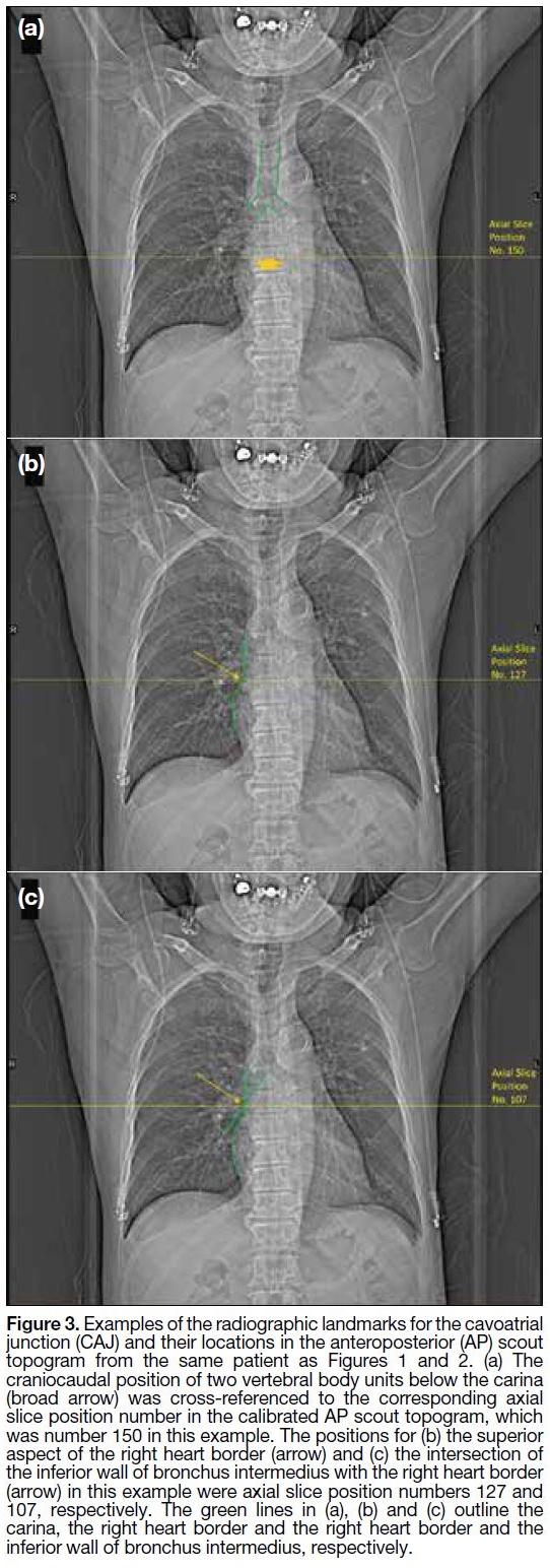
evaluated the scout topogram without knowing the position of the CAJ determined by the CTA. For each
study, readers determined the location of the three
interested radiographic landmarks on the AP scout
topogram, including two vertebral body units below the
carina (Figure 3a), the superior aspect of the right heart
border (Figure 3b), and the intersection of the inferior
wall of the bronchus intermedius with the right heart
border (Figure 3c). The craniocaudal locations of these
radiographic landmarks were recorded. If a radiographic
landmark was not visible in the AP scout topogram, the
position of this landmark was recorded as ‘indeterminate’
with reason provided.
Figure 3. Examples of the radiographic landmarks for the cavoatrial
junction (CAJ) and their locations in the anteroposterior (AP) scout
topogram from the same patient as Figures 1 and 2. (a) The
craniocaudal position of two vertebral body units below the carina
(broad arrow) was cross-referenced to the corresponding axial
slice position number in the calibrated AP scout topogram, which
was number 150 in this example. The positions for (b) the superior
aspect of the right heart border (arrow) and (c) the intersection of
the inferior wall of bronchus intermedius with the right heart border
(arrow) in this example were axial slice position numbers 127 and
107, respectively. The green lines in (a), (b) and (c) outline the
carina, the right heart border and the right heart border and the
inferior wall of bronchus intermedius, respectively.
Statistical Analysis
All statistical analyses were performed using commercial
software SPSS (Windows version 27; IBM Corp,
Armonk [NY], United States). Intra-class correlation
(ICC) was analysed using a two-way random effects
model with emphasis on consistency for determination of
inter-observer reliability so as to generalise the reliability
results to any raters who possess the same characteristics
as the selected raters in the reliability study.
Data were initially assessed for normality with the
Shapiro–Wilk test. Based on these results, a non-parametric
procedure was employed for comparison
between groups as parametric test cannot be used in
the present study. The vertical distances between these
landmarks and the CAJ are reported as median and range. The non-parametric Kruskal–Wallis test was used to test
for overall equality of medians in each data group. The
significance level (α) was adjusted by the Bonferroni
correction in view of multiple comparisons, where a
p value of 0.0167 (0.05/3) was considered to indicate a
significant difference.
RESULTS
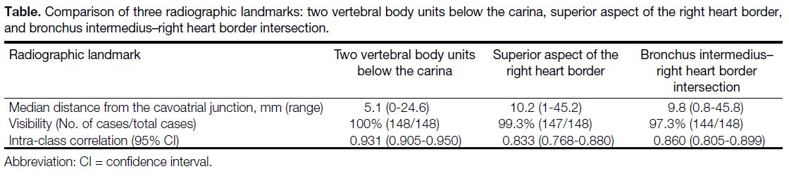
Results are summarised in the Table. There were 63 male
(42.6%) and 85 female (57.4%) patients. The median
age at the time of examination was 62 years (range,
32-86). The radiographic landmark ‘two vertebral body
units below the carina’ was visible in all 148 cases.
The superior aspect of the right heart border was not
visible in one case due to rotation of patient resulting
in overlapping of the right heart border and the spine.
The intersection of the inferior wall of the bronchus
intermedius with the right heart border was not clearly
visible in four patients due to rotation or branching of
the bronchus intermedius proximal to the right heart
border.
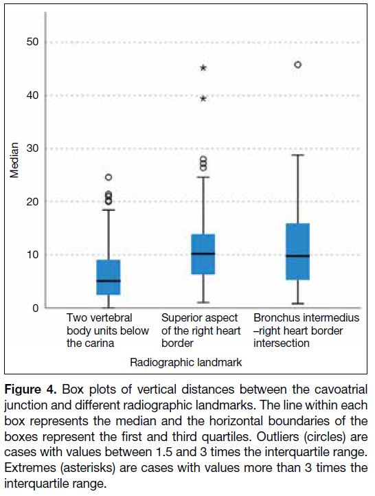
The vertical distances between the above landmarks
and the CAJ are presented as box plots (Figure 4).
The median vertical distances between the CAJ and
two vertebral body units below the carina, the superior
aspect of the right heart border, and the intersection
of the inferior wall of the bronchus intermedius with
the right heart border were 5.1 mm (range, 0-24.6),
10.2 mm (range, 1-45.2) and 9.8 mm (range, 0.8-45.8),
respectively. Using the superior aspect of the right heart
border as the surrogate of the CAJ yielded extreme
discrepancy in two patients (39.4 and 45.2 mm),
while using the intersection of the inferior wall of the
bronchus intermedius with the right heart border created
a discrepancy of 45.8 mm in one patient, close to the
limit of 3 interquartiles. The median vertical distance
between the CAJ and two vertebral body units below the
carina was significantly shorter than that of the other two
landmarks (p < 0.001) according to the Kruskal–Wallis
test. There was no significant difference in the median
vertical distance between the CAJ and the superior
aspect of the right heart border and that between the CAJ
and the intersection of the inferior wall of the bronchus
intermedius with the right heart border (p = 0.977).
Figure 4. Box plots of vertical distances between the cavoatrial
junction and different radiographic landmarks. The line within each
box represents the median and the horizontal boundaries of the
boxes represent the first and third quartiles. Outliers (circles) are
cases with values between 1.5 and 3 times the interquartile range.
Extremes (asterisks) are cases with values more than 3 times the
interquartile range.
Inter-observer agreements for determination of the three
radiographic landmarks were all excellent. As shown
in the Table, the highest inter-observer agreement was
obtained when using two vertebral body units below
the carina as a radiographic landmark (ICC = 0.931,
95% confidence interval [CI] = 0.905-0.950), as
compared with that of the superior aspect of the right
heart border (ICC=0.833, 95% CI = 0.768-0.880) and
the intersection of the inferior wall of the bronchus
intermedius with the right heart border (ICC = 0.860,
95% CI = 0.805-0.899).
Table. Comparison of three radiographic landmarks: two vertebral body units below the carina, superior aspect of the right heart border,
and bronchus intermedius–right heart border intersection.
DISCUSSION
Our study attempted to define the most accurate and
consistent radiographic landmark that could act as a
surrogate marker for the CAJ. We have shown that the
most reliable estimate of the location of the CAJ is two
vertebral body units below the carina. Discrepancies
between the anatomical CAJ defined by CTA and that
using this surrogate marker were significantly smaller
than those estimated by the other two locations. The use
of two vertebral body units below the carina has also been
suggested by most prior observational studies. Baskin
et al[7] showed the mean vertical distance from the CAJ
to the carina and to two vertebral body units below the
carina were 40 ± 10 mm and 0.4 ± 8.2 mm, respectively. Similar findings were also shown by Mahlon and Yoon,[9]
with the CAJ 40.3 ± 13.6 mm below the level of the
carina. A study by Ridge et al[8] showed that the CAJ
was 42 ± 11 mm or 2.2 vertebral body units below the
carina. However, Song et al[10] found that the CAJ was
2.4 vertebral body units below the carina. We believe
such differences could be due to differences in median
age and exclusion of lung diseases in their study. In our
study, we do not exclude patients with lung disease in
order to improve generalisability of our results as patients
with lung diseases may also need placement of CVC. A
study by Aslamy et al[11] shows that the superior aspect
of the right heart border in magnetic resonance imaging
usually represents the superimposition of several
mediastinal structures, such as the hilar vessels or even
the right epicardial margin of the left atrium, indicating
it does not solely represent the CAJ. In another study by
Baskin et al,[7] the superior aspect of the right heart
border usually represents the point at which the SVC
descends posterior to the right atrial appendage. Such
findings could explain the larger discrepancies between
the anatomical CAJ and using the superior aspect of the
right heart border on chest radiographs in predicting
the actual location of the CAJ as shown in our study.
The intersection of the inferior wall of the bronchus
intermedius with the right heart border was the least
frequently visible (97.2%) landmark on scout topogram
in our study. This landmark was reported to be visible
on 71% of scout topograms in a study by Ridge et al,[8]
indicating that this landmark can be affected by rotation
of the patient, lung volume and heart size, limiting its
accuracy and inter-observer reliability.
The use of the spine as an internal reference has several advantages. The spine is only minimally affected by
geometric magnification and is adaptive to somatic
growth, which will aid in accurate catheter placement.[7]
The spinal structures and the carina are easily identified
on chest radiographs, which may translate into better
inter-observer reliability. Our study showed the inter-observer reliability for determination of two vertebral
body units in radiographs is higher than that of the other
two radiographic surrogates without overlap between the
95% CI of the ICCs. It is also worth mentioning that CVC
tips can migrate up to 2 cm cephalad to their original
position when a patient moves from the supine to the
erect position.[12] Tips may also migrate up to 2 cm caudad
to their original position if patients abduct their arms.[13]
The effects of patients’ body and arm positioning on the
catheter tip position should be considered when assessing
follow-up chest radiographs to prevent overcalling of tip
migration. In an ideal situation, standardisation of patient
positioning for chest radiographs intended for follow-up
assessment of catheter tip position should be employed.
This study has a few limitations. First, this study was
conducted in a single institution and was restricted to
South East Asians. In order to generalise our findings
to other populations, a multicentre large-scale study
should be conducted. Second, patients’ arms were in the
abducted position when CTA and AP scout topograms
were taken, which is usually not the position during CVC
placement. The resolution of a scout topogram is inferior
to conventional chest radiographs. This may have impact
on the inter-observer reliability on determination of
the radiographic landmarks. However, we believe the
image quality of scout topograms simulates the real-life
situation during CVC placement under fluoroscopic
guidance where the image resolution is similar.
CONCLUSION
Positioning of a CVC tip at the CAJ has been
recommended by many studies to avoid potentially fatal
catheter-related complications such as dysrhythmia,
cardiac perforation, and venous thrombosis. Several
radiographic landmarks have been proposed to describe
the location of the CAJ in chest radiographs. Our study
demonstrated two vertebral body units below the carina
provided the most accurate estimation of CAJ position and had the best inter-observer reliability among these
radiographic landmarks.
REFERENCES
1. Vesely TM. Central venous catheter tip position: a continuing
controversy. J Vasc Interv Radiol. 2003;14:527-34. Crossref
2. Pittiruti M, Lamperti M. Late cardiac tamponade in adults secondary to tip position in the right atrium: an urban legend? A systematic review of the literature. J Cardiothorac Vasc Anesth. 2015;29:491-5. Crossref
3. Luciani A, Clement O, Halimi P, Goudot D, Portier F, Bassot V,
et al. Catheter-related upper extremity deep venous thrombosis
in cancer patients: a prospective study based on Doppler US.
Radiology. 2001;220:655-60. Crossref
4. Amerasekera SS, Jones CM, Patel R, Cleasby MJ. Imaging of the
complications of peripherally inserted central venous catheters.
Clin Radiol. 2009;64:832-40. Crossref
5. Vesely TM, Beathard G, Ash S, Hoggard J, Schon D, ASDIN
Clinical Practice Committee. A position statement from the
American Society of Diagnostic and Interventional Nephrology.
Semin Dial. 2007;20:359-64. Crossref
6. Tip location of peripherally inserted central catheters [editorial]. J
Vasc Access Devices. 1998;3:8-10. Crossref
7. Baskin KM, Jimenez RM, Cahill AM, Jawad AF, Towbin RB.
Cavoatrial junction and central venous anatomy: implications
for central venous access tip position. J Vasc Interv Radiol.
2008;19:359-65. Crossref
8. Ridge CA, Litmanovich D, Molinari F, Bankier AA, Eisenberg RL.
Radiographic evaluation of central venous catheter position:
anatomic correlation using gated coronary computed tomographic
angiography. J Thorac Imaging. 2013;28:129-33. Crossref
9. Mahlon MA, Yoon HC. CT angiography of the superior vena
cava: normative values and implications for central venous catheter
position. J Vasc Interv Radiol. 2007;18:1106-10. Crossref
10. Song YG, Byun JH, Hwang SY, Kim CW, Shim SG. Use of vertebral body units to locate the cavoatrial junction for optimum central venous catheter tip positioning. Br J Anaesth. 2015;115:252-7. Crossref
11. Aslamy Z, Dewald CL, Heffner JE. MRI of central venous
anatomy: implications for central venous catheter insertion. Chest.
1998;114:820-6. Crossref
12. Schutz JC, Patel AA, Clark TW, Solomon JA, Freiman DB,
Tuite CM, et al. Relationship between chest port catheter tip
position and port malfunction after interventional radiologic
placement. J Vasc Interv Radiol. 2004;15:581-7. Crossref
13. Forauer AR, Alonzo M. Change in peripherally inserted central
catheter tip position with abduction and adduction of the upper
extremity. J Vasc Interv Radiol. 2000;11:1315-8. Crossref