
Magnetic Resonance Imaging Safety: Magnetic Field–Related Hazards and Safety Measures
PERSPECTIVE
Hong Kong J Radiol 2025;28:Epub 12 September 2025
Magnetic Resonance Imaging Safety: Magnetic Field–Related Hazards and Safety Measures
L Xiao1, A Li2, J Cai3, E Chan2, T Li3
1 Department of Clinical Oncology, Tuen Mun Hospital, Hong Kong SAR, China
2 Department of Radiology, Tuen Mun Hospital, Hong Kong SAR, China
3 Department of Health Technology and Informatics, The Hong Kong Polytechnic University, Hong Kong SAR,
China
Correspondence: Dr L Xiao, Department of Clinical Oncology, Tuen Mun Hospital, Hong Kong SAR, China. Email: xl430@ha.org.hk
Submitted: 22 February 2024; Accepted: 27 August 2024. This version may differ from the final version when published in an issue.
Contributors: All authors designed the study. LX, AL and EC acquired the data. All authors analysed the data. LX, AL and EC drafted the manuscript. LX, JC and TL critically revised the manuscript for important intellectual content. All authors had full access to the data, contributed to the study, approved the final version for publication, and take responsibility for its accuracy and integrity.
Conflicts of Interest: All authors have disclosed no conflicts of interest.
Funding/Support: This study received no specific grant from any funding agency in the public, commercial, or not-for-profit sectors.
Data Availability: All data generated or analysed during the present study are available from the corresponding author on reasonable request.
Abstract
Providing excellent soft tissue contrast as well as functional and metabolic information, combined with non-ionising
radiation exposure, magnetic resonance imaging (MRI) has become widely used as a powerful diagnostic tool. With
technological advances, MRI systems have evolved to include stronger static magnetic fields, faster and more powerful
gradient magnetic fields, and enhanced radiofrequency transmission coils. These stronger MRI systems have the
potential to introduce additional safety risks within the MR scanner room, even as they deliver improved efficiency
and increased image quality. On the other hand, MRI technology has rapidly expanded into additional areas in
recent years. For example, MRI is now incorporated into radiation therapy practice, as well as interventional and
intraoperative hybrid suites. With the significant expansion and rapid development of the technology, the associated
complexity and increase in MRI safety issues should be extensively studied. It is important to make great efforts to
maintain and improve safety in the MRI environment. This article aims to provide an overview, from basic science
explaining these potential risks to practical aspects of risk management, and to increase awareness of the unique
safety challenges inherent in the MRI environment.
Key Words: Magnetic fields; Magnetic resonance imaging
中文摘要
磁力共振成像安全:磁場相關風險與安全措施
肖麗、李子飛、蔡璟、陳德養、黎田
磁力共振成像可提供優良的軟組織對比度以及功能和代謝資訊,而且不涉及電離輻射,已成為廣泛應用的有效診斷工具。隨着技術進步,磁力共振成像系統不斷演變,包括更強的靜磁場、更快速且更強大的梯度磁場,以及更高效的射頻傳輸線圈。這些更強大的磁力共振成像系統在提升掃描效率和影像質素的同時,亦可能在磁力共振成像掃描室引入額外的安全風險。另一方面,近年來磁力共振成像技術已迅速擴展至其他領域,例如已被納入放射治療、介入性程序及術中混合手術室。隨着技術顯著擴展和快速發展,相關的磁力共振成像安全問題變得更加複雜,潛在風險亦日益增加,值得深入探討。積極維護和提升磁力共振成像環境的安全性至關重要。本文旨在提供概述,解釋這些潛在風險的基本知識和風險管理的實務操作,以提高大眾對磁力共振成像環境中固有獨特安全風險的認識。
INTRODUCTION
Statistical analysis shows adverse events of magnetic
resonance imaging (MRI) growing at nearly three times the
rate of MRI procedure volume growth.[1] The potential
risks in magnetic resonance (MR) are related to the
three types of magnetic fields used in magnetic
resonance imaging (MRI): the static
magnetic field (B0), the radiofrequency (RF) field (B1),
and the time-varying magnetic field gradients. Each of
the three creates both their own and combined safety
risks including projectile forces, torque force, biological
effects, biomedical implant and device risk, cryogen-related
bodily harm and asphyxiation, heat deposition
and acoustic noise—all of which have the potential to
cause significant harm or even death.
BASIC MAGNETIC RESONANCE SAFETY CONSIDERATION
The potential risks in MRI are associated with the three
major electromagnetic fields: the B0, the varying magnetic
field gradients, and the time-varying B1.[2] The ultra-low
temperature helium found in superconductive magnets
presents a risk. With the new generation of sealed, low-volume
helium scanners, handling cryogenics may not
be required.
Static Magnetic Field
Most clinical MR scanners in use today are
superconducting electromagnets with a superconducting
solenoid coil (niobium-titanium) immersed in liquid
helium at -269℃ (4°K). Even without an external power
supply, the magnet’s magnetic field remains unchanged
because the electrical resistance of superconductors
is negligible; therefore, the risk associated with the
superconductive magnetic field is always present.
Clinically available scanners have magnetic fields of
typically 1.5 or 3.0 T. It is estimated that approximately 100 ultra-high field 7-T MR scanners have been released for clinical use in
Europe and the US. The potential risks associated with
a B0 and its spatial field gradients with sharp slope near the scanner include biological effects on humans (such
as vertigo, nausea or magnetophosphenes), as well as
the translational and rotational forces acting on objects,
with the associated device displacement and medical
device disruption. For current-carrying objects, Lenz’s
force applied to the objects can result in movement in
the magnetic field; however, patients with ferromagnetic
heart valves are typically excluded from MRI.
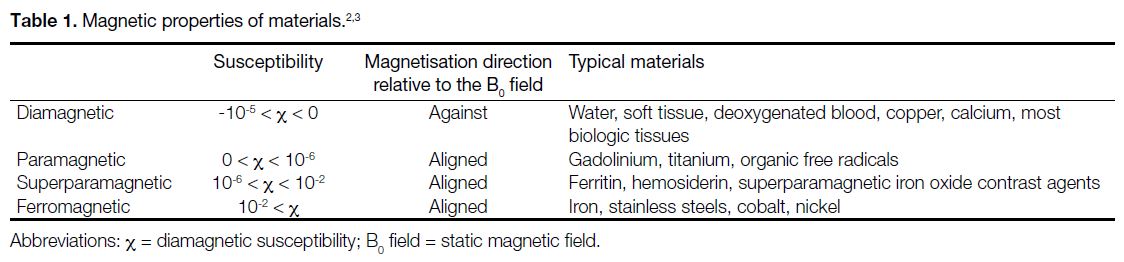
Magnetic Properties of Materials
The interaction between the magnetic field and objects
greatly depends on the magnetic properties of the materials
and their shape. Based on the behaviour of materials in
the magnetic field, materials are generally classified into
three categories: (1) diamagnetic substances such as
calcium produce negative magnetisation when placed in
an external magnetic field; (2) paramagnetic substances
acquire magnetisation in the direction of the applied
external magnetic field; and (3) ferromagnetic materials
are strongly attracted by the applied magnetic field.
Magnetic susceptibility is defined as the magnitude of
the extent to which an object becomes magnetised when
placed in a magnetic field.[3] Table 1 lists the magnetic
properties of a number of materials.[2] [3] Most biological
tissues contain a high proportion of water (H2O) and
have weakly diamagnetic susceptibility (χ), typically
around -11 × 10-6 to -7 × 10⁻⁶. Among the paramagnetic
and diamagnetic materials, the χ of most substances
encountered in routine clinical imaging lies in the range
of approximately -10-5 < χ < 10-5. Most modern implants
that claim to be MRI-safe are either diamagnetic such as
copper, or paramagnetic such as titanium.
Forces on Metal Objects
The two types of forces exerted on metal objects are
translational and rotational. The forces on diamagnetic or
paramagnetic materials are generally weak to negligible,
regardless of whether gravitational force is considered.
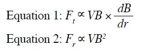
Forces on ferromagnetic objects are of paramount concern, as they experience the greatest forces in the
MR environment. The translational force (Ft) in Equation 1
increases when there are rapid changes in the magnetic
field with high spatial field gradients. It is strongest at
the edge of the magnet bore with a very sharp slope,
inversely related to the third power of the distance
(1/r3). The rotational force (Fr) is generally greatest at
the centre of the magnet bore, as it is proportional
to the square of the B0, as shown in Equation 2. V in
the equation means the volume of the metal device.
Elongated objects experience stronger torques compared
with isotropic objects. Ferromagnetic medical implants
may move rapidly in the B0, and the temporary or
permanent B0 field–induced current may be substantial
enough to hinder the normal function of electronically
powered or magnetically programmed active implanted
medical devices, such as disabling the reed switch of an
MR Conditional pacemaker.
For small asymmetrically shaped ferromagnetic objects
implanted in the body, the rotational force may become
the dominant safety issue. In a 10-year review of 1548
adverse MRI-related events reported to the US Food
and Drug Administration (FDA), 133 (9%) involved
projectiles.[4]
Bioeffects of Static Magnetic Fields
Patients or medical staff might experience vertigo,
dizziness or nausea when approaching or moving
towards the scanner. Different theories[5] [6] [7] [8] have been
proposed to explain this phenomenon in which the
Lorentz force concept is the favoured explanation.[9]
According to the Lorentz force law, Lenz’s force is
applied to the current-carrying objects when placed
inside and moving within the magnetic field. The
normal potassium-based ionic current within the middle
inner ear endolymph will experience Lenz’s force with head movement in the B0. This force is transmitted to
the ampulla, displacing the crista and hair cells of the
canal, stimulating them to generate impulses within
the vestibular nerve and resulting in vertigo. This is
the predominant source of the physiological response
associated with transient sensations of vertigo,
dizziness or nausea in MRI. The Lorentz forces are
also responsible for the magnetohydrodynamic effect.
Human blood is conductive. A Lorentz force is created
when ionic currents in the thoracic aorta flow through
the magnetic field B0. The Lorentz force deflects positive
and negative ions towards opposite sides of the vessel
when blood flows through a magnetic field. A voltage is
induced. This voltage is superimposed on the T-wave of
the electrocardiogram (ECG) used to monitor the patient
and elevates it. The distortion of the recorded ECG
by the magnetohydrodynamic effect results in faulty
cardiac triggering for cardiac MR scanning and makes
the cardiac MR examination quite challenging. This
interferes with the interpretation of the ECG that renders
it unreliable, especially when patients experience chest
pain inside the scanner.
Some MRI patients might observe the flickering lights
known as magnetophosphenes. They are generally
considered to be the result of motion-induced currents
when the eyes or head move through a B0. According
to the Faraday–Lenz law, an electric field (or current) is
induced in a conductor whenever it moves through a B0.
The induced currents directly stimulate the retina when
there is physical movement of a person’s head within the
B0. The generation of electric currents in the tongue due
to magnetically induced electric fields is viewed as the
true cause of the metallic taste experienced by patients
who undergo routine MRI examinations.[10]
Time-Varying Gradient Magnetic Fields
from the Gradient Coils
There are three orthogonal linear gradient magnetic fields (expressed in mT/m) generated by three sets of coils (one set for each of the x-, y-, and z-directions) for image
spatial encoding and contrast manipulation during image
acquisition. There is no concern about the static effects
generated by the gradient magnetic field as the strength of
the magnetic fields (the maximum amplitude per axis 40-80 mT) generated by gradients is much weaker than that
of the main magnetic field (B0). However, there are three
potential MR safety concerns associated with the time-varying
gradient magnetic field. Modern MR scanners
are equipped with powerful gradients to facilitate rapid,
high-resolution imaging or shorter echo times and echo
spacing. Gradient coils are powered by high voltage up
to 1500 V and high current of several hundred amperes
on one side. On the other side, the gradients are switched
on and off quickly with slew rates as high as 200 T/m/s in
practice. Two major physical effects and the associated
three potential MR safety concerns are produced by the
rapidly changing currents flowing through the gradient
coils.[11] The two major physical effects are mechanical
vibration of the MR system and the induced currents
in nearby conductive materials (the induced currents
are proportional to dB/dt, i.e., the rate of change of the
gradient field), respectively. The MR safety concerns
include noise, nerve/cardiac stimulation, and tissue heating.
Noise
The movement and vibration of the coils due to
mechanical forces are the primary sources of acoustic
noise in MR scanners.[12] The sound pressures generated
during routine MRI imaging can reach as high as 100 to 130
dB depending on which pulse sequences are used. It is
required and mandatory to provide hearing protection
when acoustic threshold exposure limits exceed 99 dB
by the International Electrotechnical Commission
(IEC).[13] [14] [15] Some patients have headaches and hearing
loss following MRI examinations when not wearing
appropriate hearing protection.[16] The hearing protection
should reduce noise to at least 99 dB for patients and
85 dB for personnel in the examination room. Although
concerns have been raised about MRI scans in pregnant
women due to potential risks to fetal hearing or other
effects,[17] [18] no harmful effects have been reported over
the past 30 years for those scanned during the first
trimester. Despite limited data on fetal hearing risks, it is
still recommended to establish institutional policies for
MRI exposure in pregnant patients. Pregnant healthcare
practitioners are permitted to work in and around the
MR environment throughout all stages of pregnancy.[19]
Although permitted to work in and around the MR
environment, pregnant healthcare practitioners should be advised not to remain within the MR scanner bore during
actual data acquisition or scanning.[20]
Peripheral Nerve Stimulation
According to Faraday’s law of induction as mentioned
above, time-varying magnetic fields result in the
generation of electric fields in conducting materials and
an electromotive force. The gradient switching-induced electric fields in a human subject stimulate the nerves
and muscle fibres and may cause what is referred to as
peripheral nerve stimulation (PNS).[11] [21] It is generally
reported as a tingling or tapping sensation, although the
severity of discomfort ranges from barely noticeable to
physically dangerous at the other extreme, depending
on the subject’s physiological conditions. The patient’s
overall health, nerve sensitivity, and even stress or
anxiety can affect their perception of the stimulation.[22]
Meanwhile, the intensity of nerve and muscle fibre
excitation is proportional to the dB/dt and the duration
of its application. The IEC has established limits for
gradient exposure to protect patients and subjects
against PNS and cardiac stimulation,[23] which have been
adopted by the US FDA and many other organisations.
However, PNS stimulation limits for both whole-body
and regional scans can be determined by averaging the
individual stimulation thresholds of test subjects (at
least 11 volunteers), based on studies conducted with
appropriate ethics committee approval, rather than using
derived values. The first-level controlled operating
mode is defined such that 50% of all patients experience
at least mild stimulation after reaching the stimulation
threshold, while the normal operating mode limits the
scanner to 80% of this threshold.[24] [25] Cardiac muscle
contraction requires levels of stimulation at least 10 to
100 times higher than those required for PNS, and a
subject accidentally exposed to very high levels of dB/dt would almost certainly experience warning signs of
PNS before reaching levels that pose a risk to the heart.[22]
Time-Varying Magnetic Fields and Medical
Devices
Changing magnetic fields from both RF pulses and
switched gradient fields generate electric (eddy)
currents. In the presence of a conducting medical device
or implant, thermal energy is produced both within the
implant itself and in the adjacent tissues by these eddy
currents. Heating of conducting devices and the adjacent
tissues will be discussed later for RF pulses, while the
heating due to the instantaneous power deposited by the
eddy currents from the switched gradient field (dB/dt)
will be covered here.
The degree of energy deposition can be quantified by the
specific absorption rate (SAR), which is often expressed
in units of power per mass of tissue (watts/kg). Each
manufacturer provides a conservative estimate of SAR
for all commercially available MR scanners. The SAR
values are estimated automatically using a specific
imaging protocol and patient-specific information as
input, and a warning message will appear if regulatory
limits are likely to be exceeded. Considering the factors
contributing to SAR, it can be approximated by a simple
model for the switched gradient field (Equation 3)[26] [27]:
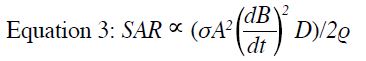
where σ is the tissue conductivity, A is the volume
of the body size, D is the duty cycle (representing the
percentage of time the gradient operates at maximum
amplitude during a sequence), and ρ is the tissue density.
Because gradient frequencies are quite low, lying in
the range of kHz, gradients do not generate appreciable
eddy currents in tissues. The thermal effects due to heat
diffusion from the implant itself may be considered, and
these effects are likely to come into play only near the
regions of maximum dB/dt for large-volume implants.[28] [29]
Time-Varying Radiofrequency Electromagnet Field
B1 is applied perpendicular to the main magnetic field (B0)
on the order of milliseconds. It tips the net magnetisation
out of alignment with B0 and MR signals are produced.
B1 is weak (μT) and oscillates at a frequency in the
MHz range matching that of a proton, with resonance
frequencies of approximately 64 MHz and 128 MHz
for 1.5 T and 3.0 T, respectively. The primary safety
concerns at these frequencies are whole-body and
localised heating from the deposition of the RF energy.[30]
In a 10-year review of 1548 adverse MRI-related events
reported to the US FDA, 906 (59%) involved thermal
injury, making it the most prevalent reported injury.[4]
According to Maxwell’s Laws, the time-varying B1 is
the source of an induced changing electric field. Such
field deposits energy into tissues, and the power applied
to tissue is generally a function of field strength, pulse
sequence, and patient size. The primary safety concerns
are the whole-body temperature increases due to heating
absorbed in the patient and the potential for tissue
damage from localised high-temperature exposures.[31] [32] [33] [34]
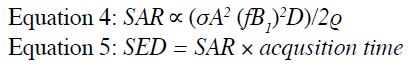
As internal temperature measurement is not easily
performed during routine clinical MRI, SAR or specific
energy dose (SED), which reflects the total
energy delivered into the patient during the active scan period, is used to control system power output in modern
MRI. This is approximated by Equations 4 and 5.
Some MR manufacturers now compute and report both
SAR and SED to limit scanning during a full exam if
the accumulated SED is too high. In addition to the
dosimetric unit used for diffusion heating over a large
volume, B++1rms (the root mean square value of B+1) is used
as an supplemental metric to SAR, which may be a better
exposure measure for focal heating because it is more
closely related to the induced electrical field and is less
dependent on the patient. The major use of B++1rms is for
MR Conditional implants. Implant manufacturers are
responsible for providing the value for the safe use of
their devices in an MR scanner.
It is generally believed that three physical mechanisms
underlie RF-induced thermal injury.[31] [35]
Radiofrequency-Induced Inductive Heating
Both the human body and metallic foreign bodies are
conductors. The currents induced by RF excitation in
modern MRI reside almost entirely along the surface
of the conductive materials, or along the conductive
loop if there are no areas of high resistance. The eddy
currents induced by the changing RF magnetic fields
are channelled into areas of high resistance (such as a
metal-skin interface or breaks in the loop); however, the
primary concern is that these current distributions can
lead to resistive heating of tissue and RF burns.[36] This
is analogous to resistive energy loss in a conventional
electrical circuit governed by Ohm’s Law. Resistive
heating in tissue is a function of material conductivity,
geometry, and location within the excitation coil.
Implants located closer to the edge of the coil tend to
experience higher electric fields. The skin itself is
conductive, and skin-to-skin contact can lead to a high
current concentration. The associated energy deposited
may be substantial enough to cause tissue damage.[37] The
point of contact is a potential region of high resistance
where significant heating can occur.[38] For example,
crossing of legs, ankle to ankle, thigh to thigh, and so on.
This phenomenon is particularly relevant when patients
are under general anaesthesia in an intraoperative MRI.
For smaller-sized conducting materials (<2 cm), there is no great concern for significant heating issues if there
are no adjacent conductors within approximately 3 cm.[39]
Otherwise, there may be enhanced heating due to coupling effects. Larger and smoother conductors can
generate a significant amount of current. These currents
flow through only a tiny fraction of the total implant
mass at its surface and do not cause significant heating
of the implant itself. In soft tissues immediately adjacent
to the implant or at sharp corners or disconnects, or when
in close proximity to another conductor, however, RF-induced
currents can become concentrated and resistive
heating may occur.[28] [29] [40] Several cases of thermal tissue
damage caused by implants have been reported, such
as from a deep brain stimulator and MR Conditional
intracranial pressure monitoring devices.[41] [42] These
examples highlight the importance of strictly adhering to
the manufacturer’s guidelines.
Heating of a Resonant Loop
In some cases, certain electrical circuits might exhibit
resonance absorption and release energy at a specific
resonance frequency. It is a relatively uncommon
situation. However, if the electrical circuits contain both
capacitance and inductance elements to form resonant
loops, they may generate a very large amount of current
and a high level of inductive heating through resonant
absorption and energy release at a resonance frequency.[43]
This situation applies to the use of ECGs with cables or
similar loops.
Antenna Effect
Another mechanism for RF heating is the so-called
antenna effect. Straight wires and elongated conductive
objects can act like antennas, capturing electromagnetic
waves to extract power from them. According to antenna
theory, the length of the wire or object must be sufficient
to support the formation of standing waves and produce standing-wave patterns of voltage and current that are
concentrated near their tips. Typically, when the length
is close to one-half of the RF wavelength, maximum
heating may be produced at the tips of the device. For
MRI, the relevant length is approximately 26 cm at 1.5 T
and 13 cm at 3.0 T. There have been incidents resulting
in fire and patient burn injuries ascribed to the antenna
effect of ECG leads and cardiac pacing leads as well.[44]
For MR safety, evaluation of impact on patient, fetus,
family and staff, as well as interaction with auxiliary
equipment and medical devices, is of constant
concern. The electromagnetic field–related hazards are
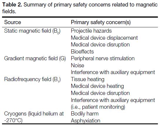
summarised in Table 2.
Table 2. Summary of primary safety concerns related to magnetic fields.
MEASURES AND MAGNETIC RESONANCE IMAGING SAFETY CHECKING PROCEDURES
Given the risks associated with the MR environment, it
is essential to take effective measures and procedures
to keep all personnel including patients, accompanying
family members, and staff safe, and to ensure all auxiliary
medical equipment and devices remain functional.
Safety Zones
The American College of Radiology (ACR) has
divided the MRI suite into four zones corresponding
to the potential safety concerns.[45] [46] The purpose of this
definition is to prevent unqualified staff and unscreened
patients from accessing hazardous areas and to restrict
MR-unsafe medical equipment or devices from being
wrongly brought into the MR scanner room. There are
other alternative schemes such as the three-area definition
from the United Kingdom or Netherlands[47]; however, the
ACR zone definition is widely adopted throughout the
world.
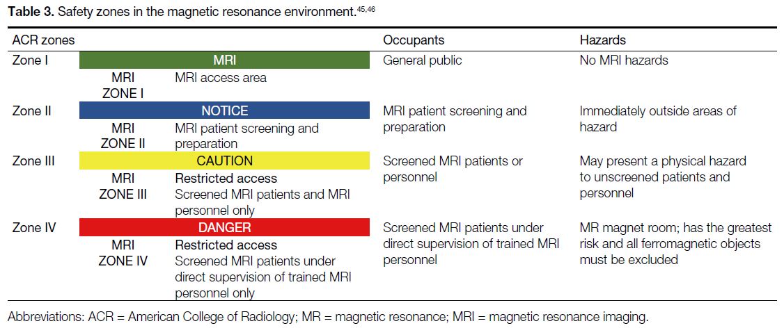
As shown in Table 3,[45] [46] Zone I is a public area that the general public can access freely without supervision,
where the fringe field is less than 5 gauss. Zone II
is a buffer area between Zones I and III for patient
preparation and safety screening. Zone III is the area near
the magnet room with potential hazards to unscreened
patients and personnel; physical barriers are used to
help control access. Zone IV is the MR scanning room
with the highest risk, where all ferromagnetic objects
are forbidden. Only properly screened personnel and
patients are permitted to enter this area.
During the early implementation of MRI technology,
the 5 gauss (0.5 mT) line or area was established as the threshold to define the limit beyond which ferromagnetic
objects and the general unscreened public are strictly
prohibited. It also served as a reminder that one is
within a region where active medical device might pose
a hazard due to exposure to the electromagnetic fields
produced by MR equipment and accessories. Recently,
the 9-gauss line has been updated to indicate the standard
for identifying the ‘magnet mode’ area for certain
active implantable medical devices, particularly cardiac
devices, to prevent accidental activation or functional
changes. The International Standard IEC 60601-2-33
for MRI safety requirements was amended to reflect this
change.[23] Magnetic fields extend in all directions, and
the 9-gauss line may extend into non-MR areas above,
below, or adjacent to the MR magnet room, which
should be carefully evaluated and clearly marked to
restrict access by unauthorised personnel.[48]
Magnetic Resonance Imaging Screening and
Safety Checklist
Personnel Screening and Management
The ACR Manual on MR Safety[49] suggests that all
patients and non-MR personnel must undergo MR
safety screening when entering Zone III.[50] Trained MR
personnel have the responsibility and authority to decide
whether a patient may be cleared for scanning. For non-emergent
patients, the ACR recommends performing
at least two separate screenings before granting access
to the MR scanner room. Screening, in the form of a
questionnaire, should be available. One of the screenings
should be conducted when the examination is requested
and should include questions such as: (1) any implanted cardiac devices (pacemakers, defibrillators, valves,
stents, wires, etc.); (2) intracranial vascular coils or
aneurysm clips; (3) neurostimulators; (4) bone growth
or bone fusion stimulators; (5) cochlear implants; (6)
the possibility of intraorbital metallic foreign bodies; (7)
implanted infusion devices such as those for insulin; and
(8) orthopaedic implants.
The second level of screening should be performed
when patients themselves present to the MR suite
for MR examination. Conscious patients should be
screened at least twice, using metal detectors and verbal
questioning, before being allowed to enter the MR
scanning room (Zone IV). The screening form similar to the MR safety screening form provided by the ACR should be reviewed by staff with MR training, such
as an MR nurse. MR radiographers or technologists
should then review and evaluate the form in detail;
ideally, both parties should sign it. MR radiographers
should ask whether any device, foreign body, or implant
is present that could pose a danger in the MR room,
including both passive and magnetically or electrically
active items. For patients who are unable to answer
screening questions, such as children, it is acceptable
to question family members, guardians, health carers
or any decision makers. All patients should be asked to
change into MR-safe hospital gowns and to remove all
watches, hearing aids, hairpins, jewellery, drug delivery
patches, eye makeup, artificial lenses (especially high-technology ones, such as implanted contact lens monitors intraocular pressure with a micro-sensor), and so on.
For emergent patients, screening with a metal detector
is acceptable but it must be performed by MR-trained
personnel or MR radiographers. Before entering
the MR scanner room, all patients should undergo
final screening. The use of ferromagnetic detection
systems is recommended as an adjunct to enhance
detection of ferromagnetic materials.[49] If a patient with
a metalworking history reports the presence of metal
in the orbital area, an X-ray should be taken or their
previous X-ray history reviewed. The handheld metal
detector should have a strength of at least 1000 gauss
with the ability to detect ferromagnetic or magnetic
objects. Metal detection
equipment is helpful in screening non-MR personnel,
especially those from other medical departments who
may or may not have MR training, since they can easily
forget to remove their personal items before entering
the MR magnet room (Zone IV).[51]
For all non-MR personnel entering the MR scanner
room, for example a family member or carer who wishes
to accompany the patient, they should be screened
using the same criteria as those applied to patients. For
cleaning of scanning room, personnel who have received
basic MR safety training may perform their duties under
MR personnel supervision and only after undergoing the
same screening procedure as patients. All MR personnel
should undergo the same screening as patients to
ensure their own safety in the MR scanner room and to
protect the non-MR personnel under their supervision.
Pregnant healthcare practitioners are permitted to work
in and around the MR environment throughout all
stages of their pregnancy. Although they are allowed
to work in and around the MR environment, pregnant
healthcare practitioners are advised not to remain inside
the scanning room while data acquisition is in progress.
These recommendations are based on the
preponderance of data relating to 3T magnetic fields.
Device and Equipment Screening and Management
The US FDA introduced guidelines on testing and
labelling medical devices and implants for safety in the
MR environment, which apply to all medical devices
that might be used in the MR environment.[52]
The square green MR Safe label indicates that
the object or device is safe in all MR environments. It is
non-magnetic, non-conductive and non-metallic, posing
no known hazards in any MR environment. Caution should be taken with products marked as ‘MR SAFE’ as
some of these products have been found with metallic
components according to our experience, and should
therefore be treated with care. The round red MR Unsafe label applies
to objects or devices that pose potential harm to MRI
patients or staff under all MR circumstances, for
example, ferromagnetic objects. The triangular yellow MR Conditional
label is for devices or objects that may be used safely
in an MR environment, provided that the conditions for
safe use are fulfilled.
The MR safety profiles for all accessory devices used
in the MR suite must be well-established before being
brought into Zone IV to avoid potential safety risks to
patients undergoing MRI. All devices being used in the
MR suite should be clearly marked with their MR safety
status (i.e., MR Safe, MR Conditional, or MR Unsafe).
Any new device or replacement must be tested for
MRI safety before use in the MR scanner room. Non-clinical
incidental objects, such as ladders or home-made
phantoms (e.g., custom-built imaging test objects) with
no manufacturer or third-party MR safety test results, as
per American Society for Testing and Materials standard,[48]
should be site-tested prior to use in the MR magnet
room. Unmarked or unknown items must not be allowed
into the MR scanner room. Never assume a device’s
MR Conditional or MR Safe status unless it is clearly
documented in writing. All accessories used within the
MR magnet room must be labelled either with MR Safe
or MR Conditional. The operating conditions of the MRI
system must be fully complied with, including limits
on magnetic field strength, coils, spatial field gradient,
gradient slew rate, SAR, or/and B+1rms as shown in the
example below.
Different types of MR Conditional equipment have
varying requirements for safe use in the MR suite. It is
quite complex and impractical to label all gauss lines and
spatial gradient magnet fields on the floor. In our practice
and according to our data analysis, most MR Conditional
devices can be used outside the 150/200 gauss (yellow)
line. A simple rule we recommend is to place medical
devices as far away from the magnetic bore as possible,
provided this does not affect the physical connection
with the patient. For example, infusion pumps can
be located outside the 150/200 gauss line even if the
manufacturer’s safety label permits use within a higher
gauss field, provided the tubing is long enough to reach
the patient. This approach also accounts for the steep slope of spatial field gradients, allowing safe control
space. It is vital that medical equipment requiring
placement close to the patient and magnet core, that is,
near the 1000 gauss line (the red line), such as ventilators,
be checked by MR safety personnel to ensure that the
manufacturer’s label confirms compliance with the
maximum magnetic field or spatial gradient requirement,
as specified in the instruction for use. In addition to
the FDA MR Conditioned label, for daily operational
convenience, it is good practice for MR safety officers
to apply clear secondary labels to frequently used MR
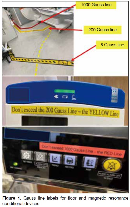
Conditional equipment. For example: “Don’t exceed the
200 gauss line (the YELLOW line).” This helps avoid
misplacement or confusion when equipment must be
moved during patient transfer, as shown in Figure 1.
These labels are for user convenience only; there is no
need for concern over the gauss line issues. In practice,
assessment and management must be carried out on a
case-by-case basis.
Figure 1. Gauss line labels for floor and magnetic resonance conditional devices.
Other suggestions for using MR Conditional devices or
objects in the MR magnet room (Zone IV) include: (1) Consider
the limits on connector tubing length and patient
positioning when placing MR Conditional or MR Safe
devices. (2) Ensure that the auto-lock brake of the device
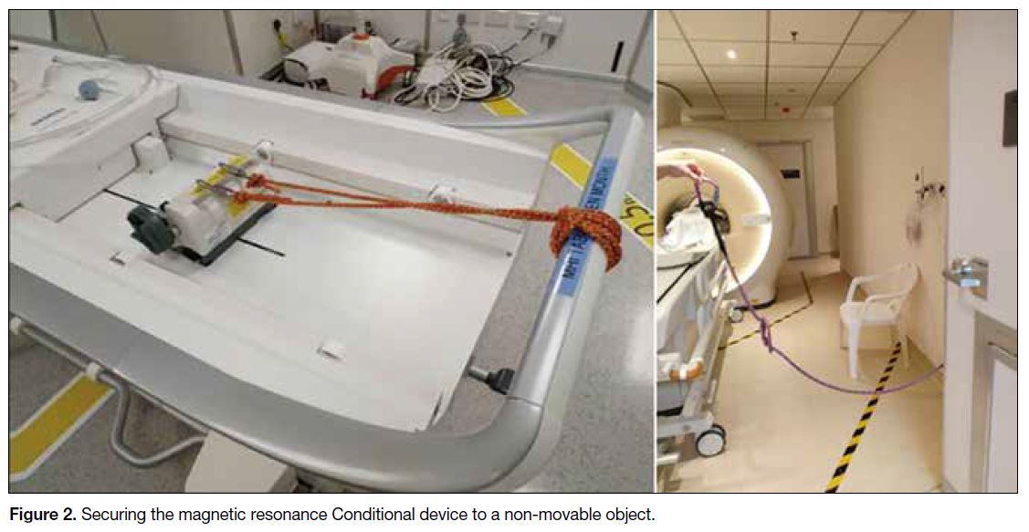
is engaged. (3) Secure the MR Conditional device to a
non-movable object if necessary, e.g., using a plastic
safety belt as shown in Figure 2.
Figure 2. Securing the magnetic resonance Conditional device to a non-movable object.
Emergency Scenario
It is recommended that MR-trained personnel manage
all emergency events, such as fire, quench, resuscitation,
etc.[53]
Resuscitation should not take place within the magnet
room (Zone IV). On-site MR-trained personnel should
remove the patient from the magnet room immediately.
Consider quenching only if there is a threatening situation
in which someone is trapped inside the magnet by a
heavy object. Close the MR magnet room door (Zone
IV) to prevent accidental access. Call for help according
to local guidelines.
If smoke or fire is coming from the scanner, equipment
room or console, on-site MR radiographers or
technologists should stop any examination procedure
immediately and evacuate the patient from the MRI
suite. Perform an emergency electrical shutdown. Do
not activate the magnet quench button unless absolutely
necessary. Close and lock the scan room door to prevent
inadvertent entry of any ferromagnetic materials into
the scan room. The incident should be announced
immediately via the intercom system. Activate the nearest
fire alarm pull station, if available. Escort all patients in
the MRI suite to a safe location. Only MR Conditional
fire extinguishers may be brought into and kept within
Zones III and IV. Firefighters must be informed of the
existence of the MRI facility and the compatibility
requirements of their fire-fighting equipment.
A quench is the procedure by which the magnetic field is
removed through the release of liquid helium. The large
volume of gaseous helium displaces oxygen in the MRI
examination room and poses a risk of asphyxiation. In
the event of a quench, stay calm and evacuate the patient.
Call for help and report the event to supervisors. Service
engineers should be contacted to assess the origin of the
fire and the condition of the scanner.
In the event of all incidents or near-incidents, on-site
trained MR radiographers and technologists should
notify supervisors and the relevant parties.
NEW CHALLENGES
Introducing MRI technology into the operating theatre
and radiotherapy settings presents new challenges,
which may be explored further in a future article.
REFERENCES
1. Gilk T. The MRI Accident Chart (2000-2020). Available from: https://gilkradiologyconsultants.com/blog/the-mri-accident-chart-2000-2020/. Accessed 1 Sep 2025.
2. Stafford RJ. The physics of magnetic resonance imaging safety. Magn Reson Imaging Clin N Am. 2020;28:517-36. Crossref
3. Schenck JF. The role of magnetic susceptibility in magnetic
resonance imaging: MRI magnetic compatibility of the first and
second kinds. Med Phys. 1996;23:815-50. Crossref
4. Delfino JG, Krainak DM, Flesher SA, Miller DL. MRI-related FDA adverse event reports: a 10-yr review. Med Phys. 2019;46:5562-71. Crossref
5. Friebe B, Wollrab A, Thormann M, Fischbach K, Ricke J, Grueschow M, et al. Sensory perceptions of individuals exposed to the static field of a 7T MRI: a controlled blinded study. J Magn Reson Imaging. 2015;41:1675-81. Crossref
6. Glover PM, Cavin I, Qian W, Bowtell R, Gowland PA. Magnetic-field–induced vertigo: a theoretical and experimental investigation. Bioelectromagnetics. 2007;28:349-61. Crossref
7. Mian OS, Li Y, Antunes A, Glover PM, Day BL. On the vertigo
due to static magnetic fields. PLoS One. 2013;8:e78748. Crossref
8. Pender DJ. A model analysis of static stress in the vestibular
membranes. Theor Biol Med Model. 2009;6:19. Crossref
9. Roberts DC, Marcelli V, Gillen JS, Carey JP, Della Santina CC,
Zee DS. MRI magnetic field stimulates rotational sensors of the
brain. Curr Biol. 2011;21:1635-40. Crossref
10. Weintraub MI, Khoury A, Cole SP. Biologic effects of 3 Tesla
(T) MR imaging comparing traditional 1.5 T and 0.6 T in 1023
consecutive outpatients. J Neuroimaging. 2007;17:241-5. Crossref
11. Schaefer DJ, Bourland JD, Nyenhuis JA. Review of patient safety in
time-varying gradient fields. J Magn Reson Imaging. 2000;12:20-9. Crossref
12. McJury M, Shellock FG. Auditory noise associated with MR procedures: a review. J Magn Reson Imaging. 2000;12:37-45. Crossref
13. Liu YM, Li XD, Li YS, Guo X, Xiao LW, Xiao QH, et al. Effect
of environmental risk factors in occupational noise exposure to
noise-induced hearing loss [in Chinese]. Zhonghua Lao Dong Wei
Sheng Zhi Ye Bing Za Zhi. 2008;26:721-4.
14. Rubak T, Kock S, Koefoed-Nielsen B, Lund SP, Bonde JP,
Kolstad HA. The risk of tinnitus following occupational noise
exposure in workers with hearing loss or normal hearing. Int J
Audiol. 2008;47:109-14. Crossref
15. Bahaloo M, Davari MH, Sobhan M, Mirmohammadi SJ,
Jalalian MT, Zare Sakhvidi MJ, et al. Hearing thresholds
changes after MRI 1.5T of head and neck. Radiol Res Pract.
2019;2019:8756579. Crossref
16. Mollasadeghi A, Mehrparvar AH, Atighechi S, Davari MH,
Shokouh P, Mostaghaci M, et al. Sensorineural hearing loss after
magnetic resonance imaging. Case Rep Radiol. 2013;2013:510258. Crossref
17. De Wilde JP, Rivers AW, Price DL. A review of the current use of
magnetic resonance imaging in pregnancy and safety implications
for the fetus. Prog Biophys Mol Biol. 2005;87:335-53. Crossref
18. Alorainy IA, Albadr FB, Abujamea AH. Attitude towards MRI
safety during pregnancy. Ann Saudi Med. 2006;26:306-9. Crossref
19. Sammet S. Magnetic resonance safety. Abdom Radiol (NY). 2016;41:444-51. Crossref
20. Maralani PJ, Kapadia A, Liu G, Moretti F, Ghandehari H,
Clarke SE, et al. Canadian Association of Radiologists
recommendations for the safe use of MRI during pregnancy. Can
Assoc Radiol J. 2022;73:56-67. Crossref
21. Davids M, Guérin B, Malzacher M, Schad LR, Wald LL. Predicting
magnetostimulation thresholds in the peripheral nervous system
using realistic body models. Sci Rep. 2017;7:5316. Crossref
22. Klein V, Davids M, Schad LR, Wald LL, Guérin B. Investigating
cardiac stimulation limits of MRI gradient coils using
electromagnetic and electrophysiological simulations in human and canine body models. Magn Reson Med. 2021;85:1047-61. Crossref
23. International Electrotechnical Commission. IEC 60601-2-33 ed 4.0.
Medical electrical equipment–Part 2-33: Particular requirements for
the basic safety and essential performance of magnetic resonance
equipment for medical diagnosis. 2022. Available from: https://webstore.iec.ch/en/publication/67211. Accessed 7 Jul 2023.
24. Reilly JP. Principles of nerve and heart excitation by time-varying
magnetic fields. Ann N Y Acad Sci. 1992;649:96-117. Crossref
25. Bourland JD, Nyenhuis JA, Schaefer DJ. Physiologic effects of intense MR imaging gradient fields. Neuroimaging Clin N Am. 1999;9:363-77. Crossref
26. Panych LP, Madore B. The physics of MRI safety. J Magn Reson Imaging. 2018;47:28-43. Crossref
27. Baker KB, Tkach JA, Nyenhuis JA, Phillips M, Shellock FG,
Gonzalez-Martinez J, et al. Evaluation of specific absorption rate
as a dosimeter of MRI-related implant heating. J Magn Reson
Imaging. 2004;20:315-20. Crossref
28. Wooldridge J, Arduino A, Zilberti L, Zanovello U, Chiampi M,
Chiampi M, et al. Gradient coil and radiofrequency induced heating
of orthopaedic implants in MRI: influencing factors. Phys Med
Biol. 2021;66:245024. Crossref
29. Arduino A, Zanovello U, Hand J, Zilberti L, Brühl R, Chiampi M,
et al. Heating of hip joint implants in MRI: the combined effect of
RF and switched-gradient fields. Magn Reson Med. 2021;85:3447-62. Crossref
30. Shellock FG. Radiofrequency energy–induced heating during MR
procedures: a review. J Magn Reson Imaging. 2000;12:30-6. Crossref
31. Foster KR, Glaser R. Thermal mechanisms of interaction of
radiofrequency energy with biological systems with relevance to
exposure guidelines. Health Phys. 2007;92:609-20. Crossref
32. Gabriel S, Lau RW, Gabriel C. The dielectric properties of
biological tissues: II. Measurements in the frequency range 10 Hz
to 20 GHz. Phys Med Biol. 1996;41:2251-69. Crossref
33. Gabriel C, Gabriel S, Corthout E. The dielectric properties
of biological tissues: I. Literature survey. Phys Med Biol.
1996;41:2231-49. Crossref
34. Gabriel S, Lau RW, Gabriel C. The dielectric properties of biological tissues: III. Parametric models for the dielectric spectrum of tissues. Phys Med Biol. 1996;41:2271-93. Crossref
35. Hoult DI, Phil D. Sensitivity and power deposition in a high-field
imaging experiment. J Magn Reson Imaging. 2000;12:46-67. Crossref
36. Batistatou E, Mölter A, Kromhout H, van Tongeren M, Crozier S, Schaap K, et al. Personal exposure to static and time-varying magnetic fields during MRI procedures in clinical practice in the UK. Occup Environ Med. 2016;73:779-86. Crossref
37. Kim SJ, Kim KA. Safety issues and updates under MR environments. Eur J Radiol. 2017;89:7-13. Crossref
38. Knopp MV, Essig M, Debus J, Zabel HJ, van Kaick G. Unusual burns of the lower extremities caused by a closed conducting loop in a patient at MR imaging. Radiology. 1996;200:572-5. Crossref
39. Song T, Xu Z, Iacono MI, Angelone LM, Rajan S. Retrospective
analysis of RF heating measurements of passive medical implants.
Magn Reson Med. 2018;80:2726-30. Crossref
40. Zilberti L, Zanovello U, Arduino A, Bottauscio O, Chiampi M.
RF-induced heating of metallic implants simulated as PEC: is there
something missing? Magn Reson Med. 2021;85:583-6. Crossref
41. Spiegel J, Fuss G, Backens M, Reith W, Magnus T, Becker G, et al.
Transient dystonia following magnetic resonance imaging in a
patient with deep brain stimulation electrodes for the treatment
of Parkinson disease. Case report. J Neurosurg. 2003;99:772-4. Crossref
42. Tanaka R, Yumoto T, Shiba N, Okawa M, Yasuhara T, Ichikawa T,
et al. Overheated and melted intracranial pressure transducer as
cause of thermal brain injury during magnetic resonance imaging:
case report. J Neurosurg. 2012;117:1100-9. Crossref
43. Abdel-Rehim S, Bagirathan S, Al-Benna S, O’Boyle C. Burns from ECG leads in an MRI scanner: case series and discussion of
mechanisms. Ann Burns Fire Disasters. 2014;27:215-8.
44. Kugel H, Bremer C, Püschel M, Fischbach R, Lenzen H, Tombach B,
et al. Hazardous situation in the MR bore: induction in ECG leads
causes fire. Eur Radiol. 2003;13:690-4. Crossref
45. Tsai LL, Grant AK, Mortele KJ, Kung JW, Smith MP. A practical
guide to MR imaging safety: what radiologists need to know.
Radiographics. 2015;35:1722-37. Crossref
46. Kanal E, Borgstede JP, Barkovich AJ, Bell C, Bradley WG,
Felmlee JP, et al. American College of Radiology White Paper on
MR Safety. AJR Am J Roentgenol. 2002;178:1335-47. Crossref
47. Medicines and Healthcare products Regulatory Agency, United Kingdom. Safety Guidelines for Magnetic Resonance Imaging Equipment in Clinical Use. 2021. Available from: https://assets.publishing.service.gov.uk/government/uploads/system/uploads/attachment_data/file/958486/MRI_guidance_2021-4-03c.pdf. Accessed 10 Sep 2025.
48. Steckner MC, Grainger D, Charles-Edwards G. Transitioning from
0.5 to 0.9 mT: Protecting against inadvertent activation of magnet
mode in active implants. Magn Reson Med. 2024;92:2237-45. Crossref
49. American College of Radiology. ACR Manual on MR Safety. 2024.
Available from: https://edge.sitecorecloud.io/americancoldf5f-acrorgf92a-productioncb02-3650/media/ACR/Files/Clinical/Radiology-Safety/Manual-on-MR-Safety.pdf. Accessed 1 Mar 2025.
50. Weidman EK, Dean KE, Rivera W, Loftus ML, Stokes TW, Min RJ.
MRI safety: a report of current practice and advancements in patient
preparation and screening. Clin Imaging. 2015;39:935-7. Crossref
51. Ponder M. Magnetic resonance safety practices: the new normal. Radiol Technol. 2015;87:109-11.
52. Shellock FG, Woods TO, Crues JV 3rd. MR labeling information
for implants and devices: explanation of terminology. Radiology.
2009;253:26-30. Crossref
53. Calamante F, Ittermann B, Kanal E; Inter-Society Working Group
on MR Safety; Norris D. Recommended responsibilities for
management of MR safety. J Magn Reson Imaging. 2016;44:1067-9. Crossref