
Exploring the Power of Hybrid Intervention: Utility of an Angio-CT System in Interventional Radiology
PICTORIAL ESSAY
Hong Kong J Radiol 2025;28:Epub 10 December 2025
Exploring the Power of Hybrid Intervention: Utility of an Angio-CT System in Interventional Radiology
CL Wong1, KKF Fung2, HY Lo1, LH Yeung1, JC Ng1, KH Lee1, DHY Cho1
1 Department of Diagnostic and Interventional Radiology, Kwong Wah Hospital, Hong Kong SAR, China
2 Department of Radiology, Hong Kong Children’s Hospital, Hong Kong SAR, China
Correspondence: Dr CL Wong, Department of Diagnostic and Interventional Radiology, Kwong Wah Hospital, Hong Kong SAR, China. Email: wcl094@ha.org.hk
Submitted: 9 October 2024; Accepted: 24 October 2024. This version may differ from the final version when published in an issue.
Contributors: All authors designed the study. CLW and DHYC acquired the data. All authors analysed the data. CLW and KKFF drafted the
manuscript, and critically revised the manuscript for important intellectual content. All authors had full access to the data, contributed to the
study, approved the final version for publication, and take responsibility for its accuracy and integrity.
Conflicts of Interest: All authors have disclosed no conflicts of interest.
Funding/Support: This study received no specific grant from any funding agency in the public, commercial, or not-for-profit sectors.
Data Availability: All data generated or analysed during the present study are available from the corresponding author on reasonable request.
Ethics Approval: This study was approved by the Clinical Research Ethics Review Board of Hospital Authority, Hong Kong (Ref No.: CIRB-2024-231-3). Informed patient consent was waived by the Board due to retrospective nature of the study.
Acknowledgement: None
INTRODUCTION
The use of cross-sectional imaging in interventional
radiology (IR) procedures is crucial for accurate target
identification, procedure planning, guidance, and
immediate therapy response monitoring.
Cone beam computed tomography (CBCT), integrated
into angiography systems with flat-panel detectors, has
been widely adopted for supplementary cross-sectional
imaging during IR procedures, in order to improve
procedural precision and safety.
Combined angiography-CT (angio-CT) systems integrate
a helical CT scanner and an angiography unit, placed on
the same rail with the same patient table. This allows
for seamless transition between CT and conventional
fluoroscopy/angiography, avoiding the need to move
the patient and its attendant risks. Besides achieving a
more efficient workflow, it also provides superior image
quality in terms of contrast resolution, noise, and artefact reduction, and a larger field of view compared to CBCT.[1]
In a study comparing the use of CBCT and angio-CT
for transarterial chemoembolisation (TACE), the overall
image quality of CT hepatic angiography in angio-CT
outperformed that of CBCT in identification of tumour
arterial feeders, reduction of streak and respiratory
artefacts, resulting in higher overall image quality.[2]
Through illustrative cases, we aim to demonstrate the
advantages of angio-CT in a wide range of vascular and
non-vascular interventions.
ANGIOGRAPHY–COMPUTED TOMOGRAPHY SYSTEM
The angio-CT (Nexaris Angio-CT; Siemens, Tubingen,
Germany) which includes a C-arm angiography system
and a helical CT scanner installed on the same rail
system (Figure 1). During procedures, the patient is
positioned with the target organ as close as possible to
the CT gantry. While the patient is lying on the IR table
for fluoroscopy or angiography, the C-arm can be moved aside to allow the CT gantry to enclose the patient during
the procedure, enabling acquisition of three-dimensional
(3D) image data that can be processed and analysed
immediately at the workstation. Immediate fusion of
3D angiography and fluoroscopy allows the operator to
navigate to the target during IR procedures such as radio-embolisation
and TACE, where precision is crucial.
Figure 1. Setting of angiography–computed tomography. The
operator can slide the computed tomography (CT) gantry around
the patient table (direction indicated by white arrow) for CT imaging
during fluoroscopy/angiography using the control panel next to the
patient table (circle).
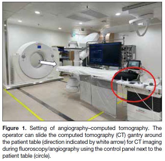
IMAGE ACQUISITION AND
INJECTION PROTOCOL CLINICAL
APPLICATIONS
Transarterial Chemoembolisation
Improving Visualisation of Small Hepatocellular
Carcinoma
Angio-CT with hepatic arteriography outperforms
diagnostic CT in terms of hepatocellular carcinoma
(HCC) visualisation.[1] [3] It can sometimes detect small
HCCs that are not conspicuous in magnetic resonance
imaging (MRI) or digital subtraction angiography
(DSA),[4] as demonstrated in the case below.
A 59-year-old hepatitis B carrier with a history of
HCCs at segments 7/8 and 6 (Figure 2 a-c) treated with
microwave ablation. During follow-up, alpha-fetoprotein
level elevated up to 10 ng/mL. Contrast MRI of the liver
showed suspicious multifocal recurrence of HCCs and
the patient was referred for TACE. Angio-CT hepatic
arteriography demonstrated superior diagnostic power
compared to DSA and MRI in detection of subcentimeter HCC with faint arterial enhancement. All lesions
demonstrated lipiodol deposition on postprocedural
CT, with complete staining, a predictive factor for good
therapeutic response to TACE.[3] Alpha-fetoprotein level
in follow-up decreased to 7.9 ng/mL (Figure 2).
Figure 2. A 59-year-old patient. (a-c) Magnetic resonance imaging of the liver with gadoxetic
acid contrast in the arterial phase shows suspicious multifocal
subcentimeter recurrent hepatocellular carcinoma in segments 6, 7
and 8 (arrows). The arrow in (c) indicates a faint arterial enhancing
focus at segment 6 near the liver edge. (d) Right hepatic artery digital
subtraction angiography shows no tumour blush in the MRI detected
lesions. (e-g) Angio-CT with intra-arterial contrast injection into the
right hepatic artery shows multiple arterial-phase enhancing lesions
corresponding to the MRI-detected tumours as seen in (a) to (c)
[arrowheads]. Chemoembolisation was performed. (h-j) Immediate
post–transarterial chemoembolisation plain CT on the angio-CT
system shows lipiodol uptake in target lesions (dashed arrows).
All lesions demonstrated lipiodol deposition on the postprocedural
scan, with complete staining seen in (i) and (j).

Improving Visualisation of Extrahepatic Arterial
Supply
For HCC cases with extrahepatic supply, studies suggest
that Angio-CT arteriography offers superior diagnostic
capability compared to conventional triphasic CT liver
and DSA.[1] [4] Its use can increase sensitivity in detecting
and confirming parasitic supply, thereby guiding
additional treatment strategies.[3] [4]
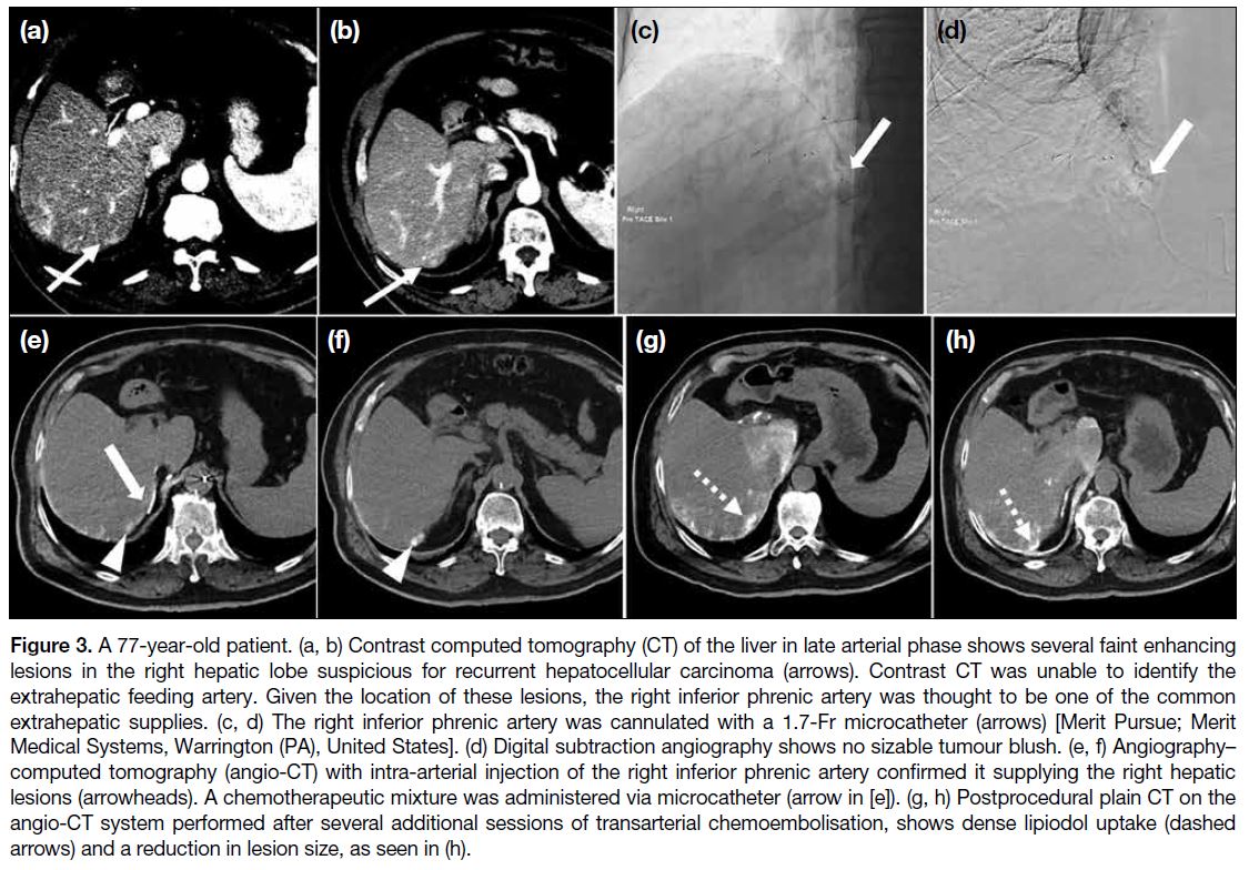
A 77-year-old hepatitis B carrier with a history of left
hepatectomy for HCC was later found to have multifocal
recurrent HCCs. Multiple TACEs were performed via
different branches of the right hepatic artery, but the
patient was still found to have persistent right hepatic
lobe HCCs on follow-up CT scan (Figure 3).
Figure 3. A 77-year-old patient. (a, b) Contrast computed tomography (CT) of the liver in late arterial phase shows several faint enhancing
lesions in the right hepatic lobe suspicious for recurrent hepatocellular carcinoma (arrows). Contrast CT was unable to identify the
extrahepatic feeding artery. Given the location of these lesions, the right inferior phrenic artery was thought to be one of the common
extrahepatic supplies. (c, d) The right inferior phrenic artery was cannulated with a 1.7-Fr microcatheter (arrows) [Merit Pursue; Merit
Medical Systems, Warrington (PA), United States]. (d) Digital subtraction angiography shows no sizable tumour blush. (e, f) Angiography–computed tomography (angio-CT) with intra-arterial injection of the right inferior phrenic artery confirmed it supplying the right hepatic
lesions (arrowheads). A chemotherapeutic mixture was administered via microcatheter (arrow in [e]). (g, h) Postprocedural plain CT on the
angio-CT system performed after several additional sessions of transarterial chemoembolisation, shows dense lipiodol uptake (dashed
arrows) and a reduction in lesion size, as seen in (h).
Enhancing Treatment Efficacy of Drug-Eluting
Bead Transarterial Chemoembolisation
In drug-eluting bead (DEB)-TACE, angio-CT offers
additional benefits beyond its higher sensitivity for
detecting viable tumour components and feeding
arteries. Unlike conventional TACE using lipiodol,
DEB-TACE does not produce lipiodol staining to assess
immediate treatment response. Therefore, an immediate
post-procedural angio-CT with intra-arterial contrast
injection can help identify residual arterial enhancement
and guide further management, such as the need for
additional drug administration.
A 64-year-old patient had a large right hepatic lobe
HCC. The lesion was too large for resection or ablation.
Hence, he underwent several episodes of TACE.
However, the patient had poor response with suboptimal
tumour lipiodol staining and rapid lipiodol washout,
and was referred for DEB-TACE. Right hepatic artery
DSA showed three suspicious arterial feeders, which
were selectively cannulated with a microcatheter (2.8Fr
Meri Maestro Swanneck microcatheter; Merit Medical
Systems, Inc, South Jordan [UT], United States). This
case demonstrated the ability of precise identification
of feeding arteries in DEB-TACE using angio-CT,
particularly for equivocal or indeterminate feeders in
DSA and preprocedural CT. It also enabled assessment
of immediate treatment response and detection of
residual lesions (Figure 4).
Figure 4. A 64-year-old patient. (a) Preprocedural contrast computed tomography liver in
late arterial phase, showing poor lipiodol staining at the anterior aspect of the lesion with a viable arterial enhancing component (dashed circle). (b) Target site 1 cannulated with microcatheter. Digital subtraction angiography showed tumour blush (arrow). (c) The arterial component was confirmed with intra-arterial injection using angiography–computed tomography (angio-CT), showing arterial blush (arrowhead). Drug-eluting beads loaded with chemomixture were administered. (d) Immediate post–drug-eluting bead transarterial chemoembolisation (DEB-TACE) angio-CT with intra-arterial injection at the feeder showing reduction in the enhancing component (arrow). (e) Digital subtraction angiography of Target site 2 shows no sizable tumour blush. (f) However, angio-CT with an intra-arterial injection shows arterially enhancing viable component (arrowhead). Drug-eluting beads loaded with chemomixture were administered. (g) Immediate post–DEB-TACE angio-CT with intra-arterial injection at feeder shows significant reduction in arterial enhancing component (arrow). (h, i) Digital subtraction angiography of Target site 3 shows no sizable tumour blush, in concordance with intra-arterial injection angio-CT showing no arterial enhancing viable component. No drug was administered at this site.

Tumour Ablation
Improving Target Visualisation
Identifying target hepatic tumours with ultrasound for
ablation can be difficult due to cirrhotic liver or prior
treatment changes. Contrast CT significantly helps with
lesion identification and ablation probe placement. Some
operators also perform intraprocedural angio-CT with
intra-arterial injection for tumour identification and
ablation margin monitoring,[1] [4] improving the precision
of ablation and treatment response monitoring.
Increasing Ease for Artificial Ascites Creation
For creation of artificial ascites, an angio-catheter is
first inserted into the peritoneal space under ultrasound
guidance, followed by a guidewire, then exchanged to a
catheter for dextrose infusion. Using angio-CT, operators
can safely manipulate the guidewire and exchange to the
catheter under real-time fluoroscopy, confirm catheter
position on CT, and proceed to image-guided ablation.
All steps involving different imaging modalities can be
performed on the same table without moving the patient.
Radiofrequency Ablation of Liver Metastases
An 85-year-old patient with a history of colonic cancer
and prior liver metastases treated with ablations. Follow-up
CT showed several new liver metastases, and the
patient was referred for image-guided radiofrequency
ablation. On-table ultrasound identified several nodules
in the right hepatic lobe, but it was difficult to distinguish
them from prior ablation zones. Triphasic angio-CT liver
showed several liver metastatic lesions (Figure 5).
Figure 5. (a-c) An 85-year-old patient. Three hypoenhancing nodules in segments 8 and 4a (circles), suggestive of liver metastases. (d-f)
For creation of artificial ascites, a 16-gauge angio-catheter (Becton Dickson, Franklin Lakes [NJ], United States) was used to target
the perihepatic space under ultrasound guidance, which was then exchanged to a 6-Fr catheter (Boston Scientific, Marlborough [MA],
United States) over a 0.035-inch Terumo guidewire (Tokyo, Japan) under fluoroscopy. The catheter tip was confirmed with angiography–computed tomography (angio-CT), followed by infusion of 5% dextrose solution. (g, h) Each lesion was targeted with an ablation antenna
under ultrasound and computed tomography guidance (antenna tips indicated by circles), with a 12-minute ablative cycle performed. (i)
Postprocedural computed tomography showing a hyperdense layer (arrow) in the artificial ascites and noted blood-stained fluid in drain. (j-l)
Immediate multiphasic images were acquired by angio-CT, showing no evidence of active bleeding or pseudoaneurysm. The patient’s vital
signs were stable and he was sent back to the ward for close observation.

Acute Haemorrhage Embolisation
Improving Detection of Bleeding Source
In cases of acute bleeding, angio-CT angiogram can
detect bleeding sources too small or slow to be identified
on CT with intravenous contrast.[1] With 3D reformatting,
the precise location of the bleeder can be accurately
determined.
Quicker Cessation of Bleeder
Unstable patients with active bleeding can be transferred
directly to angio-CT for urgent CT, followed by immediate embolisation on the same table. This
eliminates the need to move patients between the
diagnostic CT and IR suites, allowing quicker
haemorrhage control and improved outcomes.
Embolisation of Haemorrhagic Renal Tumour
A 70-year-old patient was incidentally found to have
an enhancing soft tissue mass at the lower pole of left
kidney. Ultrasound-guided biopsy was performed, but
the patient developed left flank pain with a haemoglobin
drop from 14.1 g/dL to 11.6 g/dL on day 1 post-biopsy.
Urgent CT of the kidney found intratumoural
haemorrhage and trace left haemoretroperitoneum.
Post-embolisation haemoglobin level remained stable,
with post-embolisation day 5 follow-up CT showing
no progression or active bleeding. The patient was later
discharged (Figure 6).
Figure 6. (a) A 70-year-old patient. Pre-contrast computed tomography (CT) of the kidneys shows a left renal lower pole mass with
internal hyperdensities (arrow), suggesting intratumoural haemorrhage. Arterial phase CT showed no pseudoaneurysm or active contrast
extravasation. (b) The left main renal artery was cannulated with a catheter (5Fr C1 catheter; Cordis, Miami Lakes [FL], United States) and
digital subtraction angiography performed, showing a long curved tortuous inferior segmental artery to the left lower pole (arrow), with
dysplastic distal branches. (c-e) With angiography–computed tomography, this was confirmed to be the feeding artery (arrowheads) to the
haemorrhagic renal lesion, without pseudoaneurysm or active contrast extravasation. (f) The feeder was selectively cannulated with a 2.4-Fr
microcatheter (Maestro; Merit Medical Systems, Warrington [PA], United States) with digital subtraction angiography confirming its supply
to the renal lesion (dashed arrow). Embolisation was performed with Embospheres 500-700 μm (Merit, Warrington [PA], United States) until
stasis was achieved. (g) Check of left renal angiogram showing successful occlusion of the bleeding artery.

Endoleak Detection and Management
Diagnosis for Endoleak
Angio-CT combines the benefits of DSA and CT by integrating real-time flow dynamics with detailed cross-sectional
anatomy. This allows comprehensive and
accurate evaluation of the type and site of endoleak, as
demonstrated in the following case.
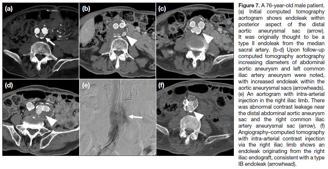
A 76-year-old male patient with infrarenal abdominal
aortic aneurysm and left common and internal iliac artery
aneurysms was managed with endovascular aneurysm
repair. A diagnostic aortogram was performed 1 year
after endovascular aneurysm repair to clarify the type
and site of endoleak. 5Fr Multipurpose catheter (Merit
Medical, South Jordan [UT], United States) was then navigated to the left iliac limb and superior mesenteric
artery, with angio-CT angiogram performed to exclude
other endoleak sites. The patient was managed with
extension of the right iliac limb endograft (Figure 7).
Figure 7. A 76-year-old male patient.
(a) Initial computed tomography
aortogram shows endoleak within
posterior aspect of the distal
aortic aneurysmal sac (arrow).
It was originally thought to be a
type II endoleak from the median
sacral artery. (b-d) Upon follow-up
computed tomography aortography
increasing diameters of abdominal
aortic aneurysm and left common
iliac artery aneurysm were noted,
with increased endoleak within the
aortic aneurysmal sacs (arrowheads).
(e) An aortogram with intra-arterial
injection in the right iliac limb. There
was abnormal contrast leakage near
the distal abdominal aortic aneurysm
sac and the right common iliac
artery aneurysmal sac (arrow). (f)
Angiography–computed tomography
with intra-arterial contrast injection
via the right iliac limb shows an
endoleak originating from the right
iliac endograft, consistent with a type
IB endoleak (arrowhead).
Embolisation of Endoleak
Angio-CT is useful for endoleak treatment. A CT
aortogram with intra-arterial injection enables precise
localisation of the endoleak, followed by targeting
under combined CT and fluoroscopic guidance, and
embolisation under real-time fluoroscopy. Final
placement of embolic material and any immediate complications can be verified with angio-CT. The system
allows the entire multimodality process to be performed
on the same table.
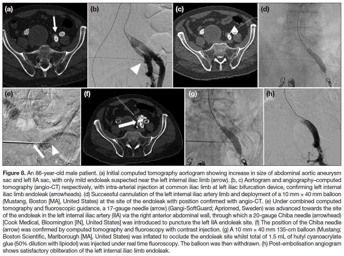
An 86-year-old male patient with an infrarenal abdominal aortic aneurysm, bilateral common iliac artery and IIA
aneurysms was treated with endovascular aneurysm
repair, right IIA coil embolisation and left iliac bifurcation
device. The endoleak was targeted for balloon-assisted
percutaneous transluminal glue embolisation in the same session. With angio-CT enabling seamless, efficient
transition between CT angiogram and fluoroscopy, the
operator safely targeted the endoleak site for embolisation
without injuring adjacent organs or damaging the stent
(Figure 8).
Figure 8. An 86-year-old male patient. (a) Initial computed tomography aortogram showing increase in size of abdominal aortic aneurysm
sac and left IIA sac, with only mild endoleak suspected near the left internal iliac limb (arrow). (b, c) Aortogram and angiography–computed
tomography (angio-CT) respectively, with intra-arterial injection at common iliac limb at left iliac bifurcation device, confirming left internal
iliac limb endoleak (arrowheads). (d) Successful cannulation of the left internal iliac artery limb and deployment of a 10 mm × 40 mm balloon
(Mustang, Boston [MA], United States) at the site of the endoleak with position confirmed with angio-CT. (e) Under combined computed
tomography and fluoroscopic guidance, a 17-gauge needle (arrow) (Gangi-SoftGuard; Apriomed, Sweden) was advanced towards the site
of the endoleak in the left internal iliac artery (IIA) via the right anterior abdominal wall, through which a 20-gauge Chiba needle (arrowhead)
[Cook Medical, Bloomington [IN], United States] was introduced to puncture the left IIA endoleak site. (f) The position of the Chiba needle
(arrow) was confirmed by computed tomography and fluoroscopy with contrast injection. (g) A 10 mm × 40 mm 135-cm balloon (Mustang;
Boston Scientific, Marlborough [MA], United States) was inflated to occlude the endoleak site whilst total of 1.5 mL of hutyl cyanoacrylate
glue (50% dilution with lipiodol) was injected under real time fluoroscopy. The balloon was then withdrawn. (h) Post-embolisation angiogram
shows satisfactory obliteration of the left internal iliac limb endoleak.
Other Cross-Modalities Applications
Percutaneous Embolisation of Pulmonary Vein
Pseudoaneurysm
The angio-CT system is valuable in complex IR cases
requiring precise target localisation with CT and
real-time fluoroscopic guidance, as illustrated in the
following case. An 88-year-old patient with multiple
co-morbidities and a history of Stanford type A aortic
dissection managed conservatively was admitted with
haemoptysis of 50 to 100 mL/day. Haemoglobin level
dropped from 10.8 g/dL to 7.7 g/dL despite on transamin
and repeated blood transfusions. He required oxygen
support at 2 L/min via mask. An urgent CT aortogram
was performed, and the patient was referred for
angiogram for lesion characterisation and subsequent
management. His condition improved, with haemoptysis
level reduced to 10 mL/day. Haemoglobin level remained stable at 7 to 8 g/dL and oxygen support was weaned off (Figure 9).
Figure 9. (a) An 88-year-old patient. Urgent computed tomography aortogram showing pulmonary consolidation and haemorrhage in the
left lower lobe, with a 0.9-cm enhancing lesion within the consolidation (arrow). It is closely abutting the left inferior pulmonary vein, raising
suspicion of a pulmonary venous pseudoaneurysm. Known Stanford type A aortic dissection was static with no mediastinal haematoma. (b,
c) Left pulmonary angiogram shows no corresponding lesion in the left lower lobe in pulmonary arterial and parenchymal phases. (d, e) An
enhancing nodule in the left lower lobe appeared after pulmonary arterial and parenchymal phases (arrowhead in [d]), consistent with the
computed tomography (CT) findings that it originated from the left inferior pulmonary vein rather than pulmonary artery. The location was
confirmed in angiography–computed tomography (circle in [e]) for embolisation planning. (f, g) Under combined fluoroscopic and computed
tomography guidance, a 20-gauge Chiba needle (Cook Medical, Bloomington [IN], United States) was used to percutaneously access
the pseudoaneurysm sac. Under fluoroscopy, contrast injection confirmed needle positioning with opacification of the pseudoaneurysm
sac (arrow in [f]) and the outflowing pulmonary vein (arrowhead in [g]). (h, i) Two 4 mm × 10 cm embolisation coils (Concerto; Medtronic,
Minneapolis [MN], United States) [circle in (h)] were successfully deployed under fluoroscopy, with coil position confirmed with computed
tomography (circle in [i]). (j) Further attempt coiling of aneurysm was not successful. 0.6 mL of hutyl cyanoacrylate glue (50% dilution
with lipiodol) was injected under fluoroscopy for complete sac embolisation. (k) Postprocedural computed tomography shows complete
obliteration of the pseudoaneurysm by glue and coils without residual contrast opacification (circle).

This case demonstrates successful lesion targeting
using a percutaneous approach, where reliance on either
fluoroscopy or intermittent CT alone poses a high risk
of injury to vital internal organs. With the advantage
of angio-CT allowing seamless transition between
CT and fluoroscopy, the operator safely punctured the
target without harming surrounding organs, followed by
embolisation under real-time fluoroscopy.
Adrenal Venous Sampling
Recognition and cannulation of the right adrenal
vein is one of the most challenging aspects of adrenal
venous sampling (AVS). Common issues include
catheter dislodgement, incorrect or deep cannulation, or
anatomical variants like an accessory hepatic vein that
may dilute cortisol. In such cases, CT during AVS can
help delineate anatomy and confirm catheter position.[5]
Compared to CBCT, CT offers superior image quality
and faster acquisition, reducing the risk of catheter
dislodgement. A case illustration is presented below.
A 42-year-old female patient with primary
hyperaldosteronism and hypertension previously failed
AVS, as the right adrenal venous sample lacked sufficient
cortisol to meet the required selectivity index, despite
venography showing a typical spidery configuration
on retrospective review. The cause of failure was
indeterminate and she was referred for a second AVS.
Angio-CT right venogram was performed before and just
after right sampling to: (1) ensure correct cannulation of
the right adrenal vein; (2) ensure the catheter remained in situ during sampling; and (3) exclude anatomical
variants such as an accessory hepatic vein. Post-sampling
angio-CT confirmed catheter position. Sampling of
right adrenal veins was successful reaching a selectivity
index of 15. The patient was diagnosed with a left-sided
aldosterone-secreting tumour and is pending surgery
(Figure 10).
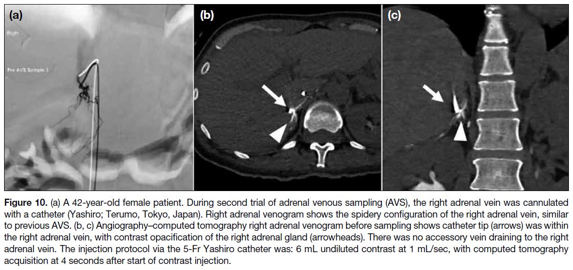
Figure 10. (a) A 42-year-old female patient. During second trial of adrenal venous sampling (AVS), the right adrenal vein was cannulated
with a catheter (Yashiro; Terumo, Tokyo, Japan). Right adrenal venogram shows the spidery configuration of the right adrenal vein, similar
to previous AVS. (b, c) Angiography–computed tomography right adrenal venogram before sampling shows catheter tip (arrows) was within
the right adrenal vein, with contrast opacification of the right adrenal gland (arrowheads). There was no accessory vein draining to the right
adrenal vein. The injection protocol via the 5-Fr Yashiro catheter was: 6 mL undiluted contrast at 1 mL/sec, with computed tomography
acquisition at 4 seconds after start of contrast injection.
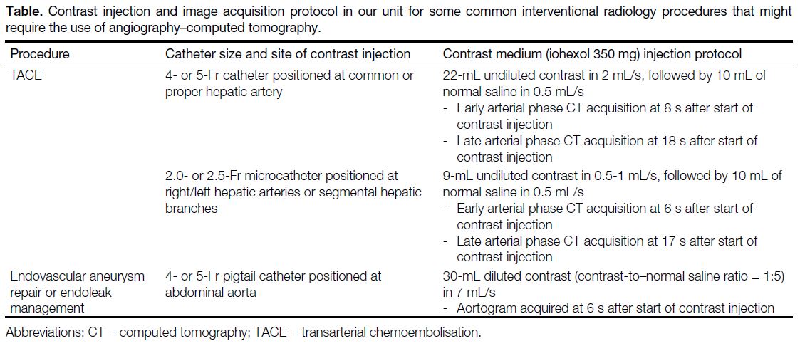
Details of the contrast injection and image acquisition
protocols for commonly performed vascular procedures requiring CT acquisition with our angio-CT system are
provided in the Table.
Table. Contrast injection and image acquisition protocol in our unit for some common interventional radiology procedures that might require the use of angiography–computed tomography
DISCUSSION
The above cases highlight the applications and
advantages of using the angio-CT system in various
IR procedures. Compared to CBCT previously used in
our unit, the image quality of CT hepatic angiogram in
angio-CT surpasses CBCT in visualisation of tumour,
identification of tumour arterial feeders, reduction of
streaking artefacts, wider field of view including the whole liver, fewer respiratory motion artefacts, and
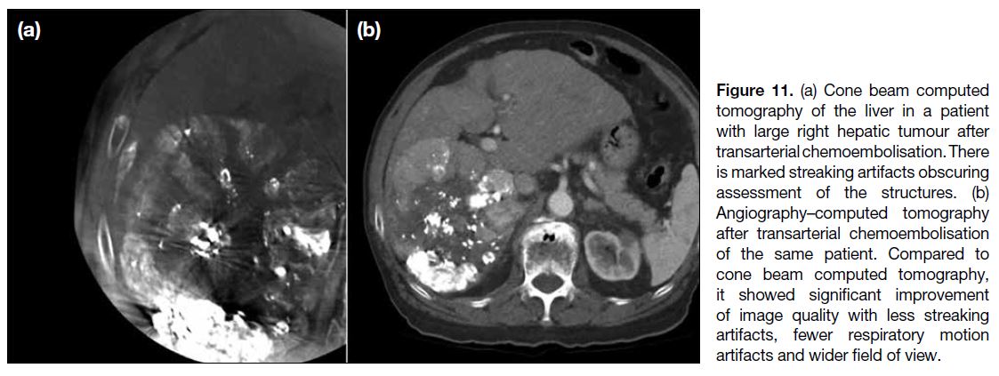
higher overall subjective image quality[2] (Figure 11). It
also allows immediate postprocedural imaging to assess
treatment response, such as immediate lipiodol uptake
and presence of residual lesions, which are limited by
streaking and respiratory artefacts in CBCT.
Figure 11. (a) Cone beam computed
tomography of the liver in a patient
with large right hepatic tumour after
transarterial chemoembolisation. There
is marked streaking artifacts obscuring
assessment of the structures. (b)
Angiography–computed tomography
after transarterial chemoembolisation
of the same patient. Compared to
cone beam computed tomography,
it showed significant improvement
of image quality with less streaking
artifacts, fewer respiratory motion
artifacts and wider field of view.
For angio-CT hepatic arteriogram, a smaller amount of
contrast can be used for direct hepatic artery injection
compared to systemic intravenous injection.[4] [5] In DEB-TACE,
multiple contrast injections are typically required to verify target lesions. Therefore, using angio-CT may
help reducing fluid overload and contrast load, which
is beneficial to patients with liver cirrhosis with pre-existing
fluid status disturbances.
In suspected complications during or immediately after
IR, angio-CT can be promptly performed with multiphasic
studies to detect bleeding, without transferring the patient
to diagnostic CT. This allows immediate diagnosis and
treatment, such as urgent embolisation.
Apart from the above examples, angio-CT can improve
procedural outcomes in the following scenarios.
A common application is combined TACE and ablation
for liver cancers, where TACE is first performed first
to devascularise and stain the tumour, followed by
ablation in the same session. The ablation margin can
be monitored during and after with intra-arterial contrast
injection, improving margin visualisation.
In hypervascular soft tissue or bone tumours, such
as renal cell or thyroid carcinoma bone metastases,
embolisation can be done first under angiography to
reduce its vascularity, followed by CT-guided ablation
in the same session. This reduces haemorrhagic risks,
especially in hypervascular tumours.[5] [7]
In emergencies requiring urgent embolisation, such
as trauma or ruptured HCC, the patient can be directly
transferred to angio-CT for urgent CT angiogram and
embolisation. After reviewing images on the angio-CT workstation, the operator can proceed immediately
without transferring the patient from diagnostic
CT to IR suite. This is crucial when the patient is
haemodynamically unstable and also shortens scan-to-needle
time, potentially improving outcomes.
A major drawback of angio-CT is cost and space.
Depending on vendor and performance, angio-CT is
approximately 1.5 to 2 times more expensive than flat
panel CBCT.[8] It also requires more space compared with
C-arm CBCT, possibly needing re-design of the IR suite.
Radiation dose between angio-CT and CBCT remains
debated. A study on CT-guided lung biopsy showed
angio-CT delivered 1.2 to 1.7 times higher effective
dose than CBCT (mean: 15.77 mSv vs. 10.68 mSv).[9]
However, another study during TACE showed angio-CT
had 2.5 times lower effective dose than CBCT (median:
15.4 vs. 39.2 mSv).[10] Dose indices differ: angio-CT uses
dose-length product while CBCT uses dose-area product.
As these comparisons were based on estimated effective
doses using region-specific conversion factors and
phantom calculations, uncertainties must be considered
when interpreting dosage results.
The integration of angiography unit and dedicated CT
scanner into a hybrid angio-CT system is a revolutionary
technology for IR. By enabling detailed anatomical
characterisation and visualisation of critical structures,
angio-CT is a valuable tool to enhance the patient
outcome and reduce procedural risks in complex
interventional procedures.
REFERENCES
1. Taiji R, Lin EY, Lin YM, Yevich S, Avritscher R, Sheth RA, et al.
Combined angio-CT systems: a roadmap tool for precision
therapy in interventional oncology. Radiol Imaging Cancer.
2021;3:e210039. Crossref
2. Lin EY, Jones AK, Chintalapani G, Jeng ZS, Ensor J, Odisio BC.
Comparative analysis of intra-arterial cone-beam versus
conventional computed tomography during hepatic arteriography
for transarterial chemoembolization planning. Cardiovasc Intervent
Radiol. 2019;42:591-600. Crossref
3. Wang H, Han Y, Chen G, Jin L. Imaging biomarkers on angio-CT for predicting the efficacy of transarterial chemoembolization in
hepatocellular carcinoma. Quant Imaging Med Surg. 2023;13:4077-88. Crossref
4. van Tilborg AA, Scheffer HJ, Nielsen K, van Waesberghe JH,
Comans EF, van Kuijk C, et al. Transcatheter CT arterial
portography and CT hepatic arteriography for liver tumor
visualization during percutaneous ablation. J Vasc Interv Radiol.
2014;25:1101-11.e4. Crossref
5. Kobayashi K, Ozkan E, Tam A, Ensor J, Wallace MJ, Gupta S. Preoperative embolization of spinal tumors: variables affecting intraoperative blood loss after embolization. Acta Radiol.
2012;53:935-42. Crossref
6. Puijk RS, Nieuwenhuizen S, van den Bemd BA, Ruarus AH,
Geboers B, Vroomen LG, et al. Transcatheter CT hepatic
arteriography compared with conventional CT fluoroscopy
guidance in percutaneous thermal ablation to treat colorectal liver
metastases: a single-center comparative analysis of 2 historical
cohorts. J Vasc Interv Radiol. 2020;31:1772-83. Crossref
7. Owen RJ. Embolization of musculoskeletal bone tumors. Semin Intervent Radiol. 2010;27:111-23. Crossref
8. Tanaka T, Arai Y, Inaba Y, Inoue M, Nishiofuku H, Anai H, et al.
Current role of hybrid CT/angiography system compared with
C-arm cone beam CT for interventional oncology. Br J Radiol.
2014;87:20140126. Crossref
9. Strocchi S, Colli V, Conte L. Multidetector CT fluoroscopy
and cone-beam CT-guided percutaneous transthoracic biopsy:
comparison based on patient doses. Radiat Prot Dosimetry.
2012;151:162-5. Crossref
10. Piron L, Le Roy J, Cassinotto C, Delicque J, Belgour A, Allimant C,
et al. Radiation exposure during transarterial chemoembolization:
angio-CT versus cone-beam CT. Cardiovasc Intervent Radiol.
2019;42:1609-18. Crossref